Getting Started with Targeting Intel SoC Devices
This example shows how to use the hardware-software co-design workflow to blink LEDs at various frequencies on the Arrow® SoCKit® evaluation kit.
Introduction
这个例子是一个循序渐进的指南,帮助哟u use the HDL Coder™ software to generate a custom HDL IP core which blinks LEDs on the Arrow SoCKit evaluation kit, and shows how to use Embedded Coder® to generate C code that runs on the ARM® processor to control the LED blink frequency.
You can use MATLAB® and Simulink® to design, simulate, and verify your application, perform what-if scenarios with algorithms, and optimize parameters. You can then prepare your design for hardware and software implementation on the Altera Cyclone V SoC by deciding which system elements will be performed by the programmable logic, and which system elements will run on the ARM Cortex-A9.
Using the guided workflow shown in this example, you automatically generate HDL code for the programmable logic using HDL Coder, generate C code for the ARM using Embedded Coder, and implement the design on the Intel SoC devices.
In this workflow, you perform the following steps:
Set up your Intel SoC hardware and tools.
Partition your design for hardware and software implementation.
Generate an HDL IP core using HDL Workflow Advisor.
Integrate the IP core into a Intel Qsys project and program the Intel SoC hardware.
Generate a software interface model.
Generate C code from the software interface model and run it on the ARM Cortex-A9 processor.
Tune parameters and capture results from the Intel SoC hardware using External Mode.
For more information, refer to other more advanced examples, and the HDL Coder and Embedded Coder documentation.
Requirements
Intel Quartus Prime, with supported version listed in theHDL Coder documentation
Intel SoC Embedded Design Suite
Arrow SoCKit Cyclone V SoC evaluation kit
HDL Coder Support Package for Intel SoC Devices
Embedded Coder Support Package for Intel SoC Devices
Set up Intel SoC hardware and tools
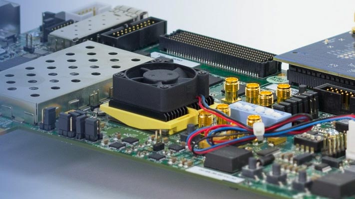
1.Set up the Arrow SoCKit evaluation kit as shown in the figure below. To learn more about the Arrow SoCKit hardware setup, please refer to the board documentation.

1.1Set upSW4switch (JTAG chain select) as shown in the figure below. Position 1 : OFF; Position 2 : ON. This configuration includes HPS in JTAG chain, and bypasses HSMC.

1.2Set upJP2as shown in the figure below to adjust the I/O Standard of the FPGA/HSMC pins. Short Pin 5 and 6 to set the I/O voltage to 2.5V.

1.3Set upJ17 - J19as shown in the figure above to boot HPS from SD card. J17: Short Pin 1 and 2; J18: Short Pin 1 and 2; J19: Short Pin 2 and 3.
1.4Set upJ15 - J16as shown in the figure above for HPS clock setting. J15: Short Pin 2 and 3; J16: Short Pin 2 and 3.
1.5Set upSW6on the back side of the board as shown in the figure below. This switch set the FPGA configuration mode. Set all 6 positions to ON.

1.6Connect your computer to the USB UART connector using a Micro-USB cable. Make sure your USB device drivers, such as for the FTDI USB to UART, are installed correctly. If not, search for the drivers online and install them.
1.7Connect your computer and the Arrow SoCKit board using an Ethernet cable.
2.Install the HDL Coder and Embedded Coder Support Packages for Intel SoC Devices if you haven't already. To start theinstaller, go to the MATLAB toolstrip and clickAdd-Ons>Get Hardware Support Packages. For more information, please refer to theSupport Package Installation documentation.
3.Make sure you are using the SD card image provided by the Embedded Coder Support Package for Intel SoC Devices. If you need to update your SD card image, refer to theHardware Setup sectionof this document.
4.Set up the Arrow SoCKit hardware connection by entering the following command in the MATLAB command window:
h = alterasoc
Thealterasocfunction logs in to the hardware via COM port and runs theifconfigcommand to obtain the IP address of the board. This function also tests the Ethernet connection.
5.You can optionally test the serial connection using the following configuration using a program such as PuTTY™. Baud rate:115200; Data bits:8; Stop bits:1; Parity:None; Flow control:None. You should be able to observe Linux booting log on the serial console when you power cycle the Arrow SoCKit board. You must close this serial connection before using thealterasocfunction again.
6.Set up the Intel Quartus synthesis tool path using the following command in the MATLAB command window. Use your own Quartus installation path when you run the command.
hdlsetuptoolpath('ToolName','Altera Quartus II','ToolPath','C:\intelFPGA\18.0\quartus\bin64\quartus.exe');
Partition your design for hardware and software implementation
The first step of the Intel SoC hardware-software co-design workflow is to decide which parts of your design to implement on the programmable logic, and which parts to run on the ARM processor.
Group all the blocks you want to implement on programmable logic into an atomic subsystem. This atomic subsystem is the boundary of your hardware-software partition. All the blocks inside this subsystem will be implemented on programmable logic, and all the blocks outside this subsystem will run on the ARM processor.
In this example, the subsystemled_counteris the hardware subsystem. It models a counter that blinks the LEDs on an FPGA board. Two input ports,Blink_frequencyandBlink_direction, are control ports that determine the LED blink frequency and direction. All the blocks outside of the subsystemled_counterare for software implementation.
In Simulink, you can use theSlider GainorManual Switchblock to adjust the input values of the hardware subsystem. In the embedded software, this means the ARM processor controls the generated IP core by writing to the AXI interface accessible registers. The output port of the hardware subsystem,LED, connects to the LED hardware. The output port,Read_Back, can be used to read data back to the processor.
open_system('hdlcoder_led_blinking_4bit');

Generate an HDL IP core using the HDL Workflow Advisor
Using the IP Core Generation workflow in the HDL Workflow Advisor enables you to automatically generate a sharable and reusable IP core module from a Simulink model. The generated IP core is designed to be connected to an embedded processor on an FPGA device. HDL Coder generates HDL code from the Simulink blocks, and also generates HDL code for the AXI interface logic connecting the IP core to the embedded processor. HDL Coder packages all the generated files into an IP core folder. You can then integrate the generated IP core with a larger FPGA embedded design in the Intel Qsys environment.
1.Start the IP core generation workflow.
1.1.Open the HDL Workflow Advisor from thehdlcoder_led_blinking_4bit/led_counter子system by right-clicking theled_counter子system, and choosingHDL Code>HDL Workflow Advisor.
1.2.In theSet Target>Set Target Device and Synthesis Tool的任务,forTarget workflow, selectIP Core Generation.
1.3.ForTarget platform, selectArrow SoCKit development board. If you don't have this option, selectGet moreto open the Support Package Installer. In the Support Package Installer, select Intel SoC Devices and follow the instructions provided by the Support Package Installer to complete the installation.
1.4.ClickRun This Taskto run theSet Target Device and Synthesis Tooltask.

1.5In theSet Target>Set Target Reference Design的任务,chooseDefault system.For this example, it is selected by default

1.6.ClickRun This Taskto run theSet Target Reference Designtask.
2.Configure the target interface.
Map each port in your DUT to one of the IP core target interfaces. In this example, input portsBlink_frequencyandBlink_directionare mapped to the AXI4 interface, so HDL Coder generates AXI interface accessible registers for them. TheLEDoutput port is mapped to an external interface,LEDs General Purpose [0:3], which connects to the LED hardware on the Intel SoC board.
2.1In theSet Target>Set Target Interface的任务,chooseAXI4forBlink_frequency,Blink_direction, andRead_back.
2.2ChooseLEDs General Purpose [0:3]forLED.

2.3In theSet Target>设置目标频率的任务,chooseTarget Frequency as 50 MHz.

3.Generate the IP Core.
To generate the IP core, right-click theGenerate RTL Code and IP Coretask and selectRun to Selected Task.

4.Generate and view the IP core report.
After you generate the custom IP core, the IP core files are in theipcorefolder within your project folder. An HTML custom IP core report is generated together with the custom IP core. The report describes the behavior and contents of the generated custom IP core.

Integrate the IP core with the Intel Qsys environment
In this part of the workflow, you insert your generated IP core into a embedded system reference design, generate an FPGA bitstream, and download the bitstream to the Intel SoC hardware.
The reference design is a predefined Intel Qsys project. It contains all the elements the Intel software needs to deploy your design to the Intel SoC devices, except for the custom IP core and embedded software that you generate.
1.To integrate with the Intel Qsys environment, select theCreate Project下任务Embedded System Integration, and clickRun This Task. Both an Intel Qsys project and an Intel Quartus project are generated, with links to the projects provided in the dialog window. You can optionally open up the projects to take a look.

2.If you have an Embedded Coder license, you can generate a software interface model in the next task,Generate Software Interface Model. The details of the software interface model are explained in the next section of this example, "Generate a software interface model".
3.Build the FPGA bitstream in theBuild FPGA Bitstreamtask. Make sure theRun build process externallyoption is checked, so the Intel synthesis tool will run in a separate process from MATLAB. Wait for the synthesis tool process to finish running in the external command window.

4.After the bitstream is generated, select theProgram Target Devicetask. ChooseDownloadforProgramming methodto download the FPGA bitstream onto the SD card on the Intel SoC board, so your design will be automatically reloaded when you power cycle the Intel SoC board. clickRun This Taskto program the Intel SoC hardware.

After you program the FPGA hardware, the LED starts blinking on your Intel SoC board.

Next, you will generate C code to run on the ARM processor to control the LED blink frequency and direction.
Generate a software interface model
In the HDL Workflow Advisor, after you generate the IP core and insert it into the Qsys reference design, you can optionally generate a software interface model in theEmbedded System Integration>Generate Software Interface Modeltask.
软件界面模型包含的一部分your design that runs in software. It includes all the blocks outside of the HDL subsystem, and replaces the HDL subsystem with AXI driver blocks. If you have an Embedded Coder license, you can automatically generate embedded code from the software interface model, build it, and run the executable on Linux on the ARM processor. The generated embedded software includes AXI driver code, generated from the AXI driver blocks, that controls the HDL IP core.
Run theGenerate Software Interface Modeltask and see that a new model is generated. The task dialog shows a link to the model.

In the generated software interface model, the "led_counter" subsystem is replaced with the AXI driver blocks which generate the interface logic between the ARM processor and FPGA.

Run the software interface model on Intel SoC hardware
In this part of the workflow, you configure the generated software interface model, automatically generate embedded C code, and run your model on the ARM processor in the Intel SoC hardware in External mode.
When you are prototyping and developing an algorithm, it is useful to monitor and tune the algorithm while it runs on hardware. The External mode feature in Simulink enables this capability. In this mode, your algorithm is first deployed to the ARM processor in the Intel SoC hardware, and then linked with the Simulink model on the host computer through an Ethernet connection.
The main role of the Simulink model is to tune and monitor the algorithm running on the hardware. Because the ARM processor is connected to the HDL IP core through the AXI interface, you can use External mode to tune parameters, and capture data from the FPGA.

In the generated model, open theConfiguration Parametersdialog box.
SelectSolver和“停止时间”设置为“正”。
From theHARDWAREmenu, click theMonitor & Tunebutton on the model toolstrip to run your model on the ARM processor in the Intel SoC hardware in External mode. Embedded Coder builds the model, downloads the ARM executable to the Intel SoC hardware, executes it, and connects the model to the executable running on the Intel SoC hardware.
Double-click theSlider Gainblock. Change the Slider Gain value and observe the change in frequency of the LED array blinking on the Intel SoC hardware. Double-click theManual Switchblock to switch the direction of the blinking LEDs.
Double-click the scope connected to theRead_backoutput port and observe that the output data of the FPGA IP core is captured and sent back to the Simulink scope.
When you are done changing model parameters, click the停止button on the model. Observe that the system command window opened in the previous step indicates that the model has been stopped. At this point, you can close the system command window.

Summary
This example shows how the hardware and software co-design workflow helps automate the deployment of your MATLAB and Simulink design to the Intel SoC devices. You can explore the best ways to partition and deploy your design by iterating through the workflow.
The following diagram shows the high-level picture of the workflow you went through in this example. To learn more about the hardware and software co-design workflow, please refer to theHDL Coder documentation.

Select a Web Site
Choose a web site to get translated content where available and see local events and offers. Based on your location, we recommend that you select:.
Selectweb siteYou can also select a web site from the following list:
Americas
- América Latina(Español)
- Canada(English)
- United States(English)
Europe
- Belgium(English)
- Denmark(English)
- Deutschland(Deutsch)
- España(Español)
- Finland(English)
- France(Français)
- Ireland(English)
- Italia(Italiano)
- Luxembourg(English)
- Netherlands(English)
- Norway(English)
- Österreich(Deutsch)
- Portugal(English)
- Sweden(English)
- Switzerland
- United Kingdom(English)