FMCW雷达的贴片天线阵列
此示例显示了如何建模77 GHz天线阵列以进行频率调节连续波(FMCW)雷达应用。随着引入无线碰撞检测,避免碰撞和车道出发警告系统,车辆内外的天线和天线阵列的存在变得司空见惯。考虑到此类系统的两个频带分别围绕24 GHz和77 GHz。在此示例中,我们将研究微带贴片天线作为梯形阵列散热器。介电衬底是空气。
This example requires the Antenna Toolbox™.
Antenna Array Design
The FMCW antenna array is intended for a forward radar system designed to look for and prevent a collision. Therefore, a cosine antenna pattern is an appropriate choice for the initial design since it does not radiate any energy backwards. Assume that the radar system operates at 77 GHz with a 700 MHz bandwidth.
FC = 77E9;fmin = 73e9;fmax = 80E9;vp = physconst(“ Lightspeed”); lambda = vp/fc; cosineantenna = phased.CosineAntennaElement; cosineantenna.FrequencyRange = [fmin fmax]; pattern(cosineantenna,fc)

The array itself needs to be mounted on or around the front bumper. The array configuration we investigate is a 2 X 4 rectangular array, similar to what is mentioned in [1]. Such a design has bigger aperture along azimuth direction thus providing better azimuth resolution.
Nrow = 2; Ncol = 4; fmcwCosineArray = phased.URA; fmcwCosineArray.Element = cosineantenna; fmcwCosineArray.Size = [Nrow Ncol]; fmcwCosineArray.ElementSpacing = [0.5*lambda 0.5*lambda]; pattern(fmcwCosineArray,fc)

Design Realistic Patch Antenna
天线工具箱具有几个天线元件,可以提供半球形覆盖范围并类似于余弦的模式。选择具有典型散热器尺寸的斑块天线元件。贴片长度约为77 GHz的一半波长,宽度是改善带宽的长度的1.5倍。地面是 在斑块长度方向的每一侧和饲料偏移量约为长度的四分之一。
PatchElement = Design(PatchMicrostrip,FC);
Because the default patch antenna geometry has its maximum radiation directed towards zenith, rotate the patch antenna by 90 degrees about the y-axis so that the maximum is along the x-axis.
patchElement.Tilt = 90; patchElement.TiltAxis = [0 1 0];
Isolated Patch Antenna 3D Pattern and Resonance
将斑块天线的图案绘制在77 GHz处。该贴片是中等增益天线,其峰值定向性约为10 dBi。
myFigure = gcf; myFigure.Color ='W';图案(PatchElement,FC)
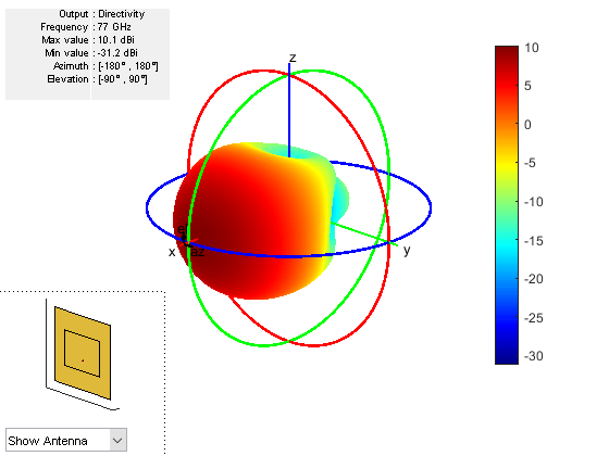
The patch is radiating in the correct mode with a pattern maximum at 0 degrees azimuth and 0 degrees elevation. Since the initial dimensions are approximations, it is important to verify the input impedance behavior.
numfreqs = 21;freqsweep = unique([linspace(fmin,fmax,numfreqs)fc]);阻抗(PatchElement,Freqsweep);

According to the figure, the patch antenna has its first resonance (parallel resonance) at 77 GHz.
接下来是检查贴片天线的反射系数,以确认良好的阻抗匹配。典型考虑价值 作为确定天线带宽的阈值。
s = sparameters(patchElement,freqsweep); rfplot(s,'m-.') holdonline(freqsweep/1e9,ones(1,numel(freqsweep))*-10,'行宽',1.5)保持off
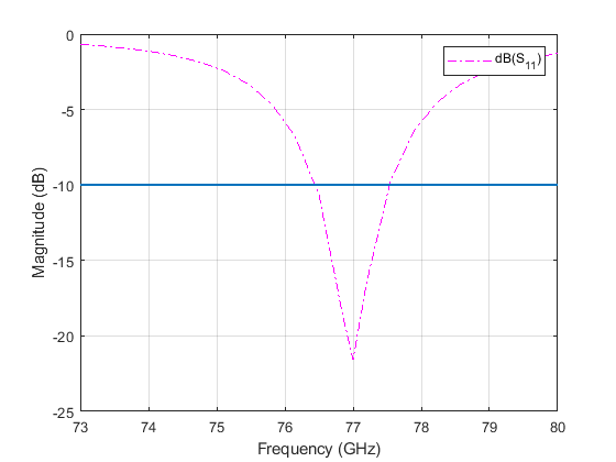
在77 GHz时的最低最小值表明与50相匹配。天线带宽略大于1 GHz。因此,频带从76.5 GHz到77.5 GHz。
最后,检查是否在边缘frequenc模式ies of the band meets the design. This is a good indication whether the pattern behaves the same across the band. The patterns at 76.5 GHz and 77.6 GHz are shown below.
图案(PatchElement,76.5E9)
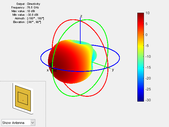
pattern(patchElement,77.6e9)

从孤立的散热器和图模式中创建数组
接下来,用贴片天线创建一个均匀的矩形阵列(URA)。选择间距是 , 在哪里is the wavelength at the upper frequency of the band (77.6 GHz).
fc2 = 77.6e9; lambda_fc2 = vp/77.6e9; fmcwPatchArray = phased.URA; fmcwPatchArray.Element = patchElement; fmcwPatchArray.Size = [Nrow Ncol]; fmcwPatchArray.ElementSpacing = [0.5*lambda_fc2 0.5*lambda_fc2];
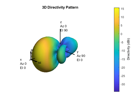
The following figure shows the pattern of the resulting patch antenna array. The pattern is computed using a 5 degree separation in both azimuth and elevation.
az = -180:5:180; el = -90:5:90; clf pattern(fmcwPatchArray,fc,az,el)
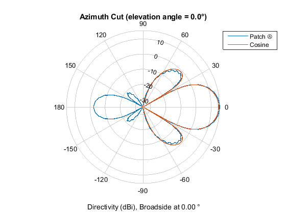
下面的图比较了贴片天线阵列和余弦元件阵列的正交平面的模式变化。请注意,两个阵列都忽略了相互耦合效果。
First, plot the patterns along the azimuth direction.
patternAzimuth(fmcwPatchArray,fc) holdonpatternAzimuth(fmcwCosineArray,fc) p = polarpattern('GCO'); p.LegendLabels = {'修补',,,,'Cosine'};
然后,沿高程方向绘制图案。
CLF Patternelevation(FMCWPATCHARRAY,FC)保持on模式增长(FMCWCOSINEARRAY,FC)p =极地图片('GCO'); p.LegendLabels = {'修补',,,,'Cosine'};
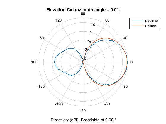
The figures show that both arrays have similar pattern behavior around the main beam in the elevation plane (azimuth = 0 deg). The patch-element array has a significant backlobe as compared to the cosine-element array.
结论
此示例启动了具有理想余弦天线的FMCW雷达天线阵列的设计,然后使用贴片天线形成真实阵列。该示例比较了两个阵列的模式,以显示设计权衡。从比较中可以看出,使用隔离贴片元件是理解现实天线元素对数组模式的效果的有用第一步。
但是,对现实阵列的分析还必须考虑相互耦合效应。由于这是一个小数组,因此阵列环境中的各个元素模式可能会显着扭曲。结果,不可能用嵌入式元素模式替换孤立的元素模式,如使用嵌入式元素模式在大阵列中建模相互耦合example. A full-wave analysis must be performed to understand the effect of mutual coupling on the overall array performance.
Reference
[1] R. Kulke等。24 GHz雷达传感器集成了斑块天线,EMPC 2005http://empire.de/main/Empire/pdf/publications/2005/26-doc-empc2005.pdf
You can also select a web site from the following list:
Americas
- América Latina(Español)
- Canada(English)
- United States(English)