Run a Vehicle Dynamics Maneuver in 3D Environment
This example shows how to run a vehicle dynamics maneuver in a 3D environment. By integrating vehicle dynamics models with a 3D environment, you can test advanced driver assistance systems (ADAS) and automated driving (AD) perception, planning, and control software. For the 3D visualization engine platform requirements and hardware recommendations, seeUnreal Engine Simulation Environment Requirements and Limitations.
Create and open a working copy of a maneuver reference application. For example, open the double-lane change reference application.
Run the maneuver simulation. By default, the 3D environment is disabled.
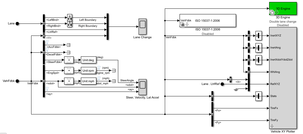
When you run the simulation, the Visualization subsystem provides driver, vehicle, and response information. The reference application logs vehicle signals during the maneuver, including steering, vehicle and engine speed, and lateral acceleration. You can use the Simulation Data Inspector to import the logged signals and examine the data.
Element Description Driver Commands
Driver commands:
Handwheel angle
Acceleration command
Brake command
Vehicle Response
Vehicle response:
Engine speed
Vehicle speed
Acceleration command
Lane ChangeScopeblock
Lateral vehicle displacement versus time:
Red line — Cones marking right lane boundary
Orange line — Cones marking left lane boundary
Blue line — Reference trajectory
Green line — Actual trajectory
Steer, Velocity, Lat AccelScopeblock
SteerAngle— Steering angle versus time
Vehicle XY Plotter
车辆纵向和横向距离
ISO 15037-1:2006block
Display ISO standard measurement signals in the Simulation Data Inspector, including steering wheel angle and torque, longitudinal and lateral velocity, and sideslip angle
Enable the 3D visualization environment. In the Visualization subsystem, open the3D Engineblock. Set these parameters.
3D EnginetoEnabled.
Scene descriptionto one of the scenes, for example
Double lane change.
To position the vehicle in the scene:
Select the position initialization method:
Recommended for scene— Set the initial vehicle position to values recommended for the scene
User-specified— Set your own initial vehicle position
ClickUpdate the model workspaces with the initial valuesto overwrite the initial vehicle position in the model workspaces with the applied values.
Rerun the reference application. As the simulation runs, in the
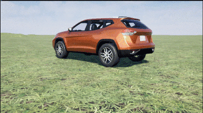
AutoVrtlEnvwindow, view the vehicle response.To smoothly change the camera views, use these key commands.
Key Camera View 1
Back left
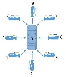
2
Back
3
Back right
4
左
5
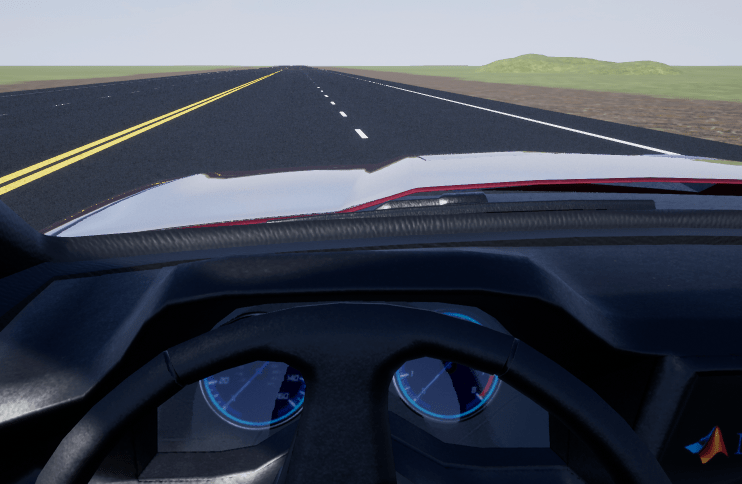
Internal
6
Right
7
Front left
8
Front
9
Front right
0
Overhead
For additional camera controls, use these key commands.
Key Camera Control Tab Cycle the view between all vehicles in the scene.
Mouse scroll wheel
Control the camera distance from the vehicle.
L
Toggle a camera lag effect on or off. When you enable the lag effect, the camera view includes:
Position lag, based on the vehicle translational acceleration
Rotation lag, based on the vehicle rotational velocity
This lag enables improved visualization of overall vehicle acceleration and rotation.
F Toggle the free camera mode on or off. When you enable the free camera mode, you can use the mouse to change the pitch and yaw of the camera. This mode enables you to orbit the camera around the vehicle.
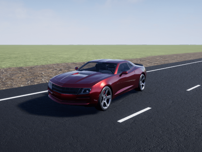
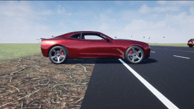
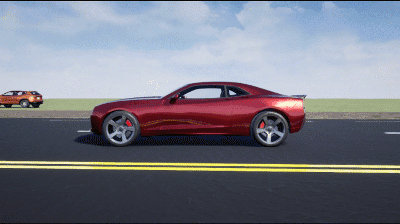
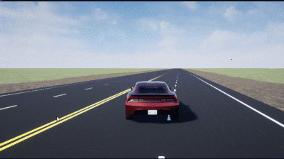
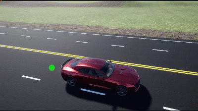
For example, when you run the double-lane change maneuver, use the cameras to visualize the vehicle as it changes lanes.
Back

Front left
Internal
Note
To open and close the
AutoVrtlEnvwindow, use the Simulink®Run and Stop buttons. If you manually close theAutoVrtlEnvwindow, Simulink stops the simulation with an error.当你使3 d可视化中的发言ent, you cannot step the simulation back.


Related Topics
You can also select a web site from the following list:
Americas
- América Latina(Español)
- Canada(English)
- United States(English)
Europe
- Belgium(English)
- Denmark(English)
- Deutschland(Deutsch)
- España(Español)
- Finland(English)
- France(Français)
- Ireland(English)
- Italia(Italiano)
- Luxembourg(English)
- Netherlands(English)
- Norway(English)
- Österreich(Deutsch)
- Portugal(English)
- Sweden(English)
- Switzerland
- United Kingdom(English)