Lane Detection
此示例显示了如何实现FPGA的通道标记检测算法。
Lane detection is a critical processing stage in Advanced Driving Assistance Systems (ADAS). Automatically detecting lane boundaries from a video stream is computationally challenging and therefore hardware accelerators such as FPGAs and GPUs are often required to achieve real time performance.
在该示例模型中,基于FPGA的车道候选发生器与基于软件的多项式拟合发动机耦合,以确定车道边界。
System Overview
该lanedetectionhdl.slx.system is shown below. The HDLLaneDetector subsystem represents the hardware accelerated part of the design, while the SWLaneFitandOverlay subsystem represent the software based polynomial fitting engine. Prior to the Frame to Pixels block, the RGB input is converted to intensity color space.

HDL Lane Detector
该HDL Lane Detector represents the hardware-accelerated part of the design. This subsystem receives the input pixel stream from the front-facing camera source, transforms the view to obtain the birds-eye view, locates lane marking candidates from the transformed view and then buffers them up into a vector to send to the software side for curve fitting and overlay.

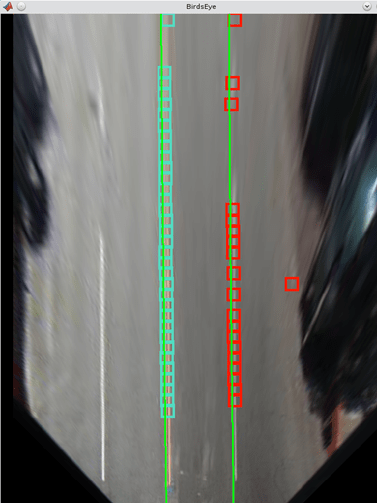
Birds-Eye View
鸟瞰块将正面的相机视图转变为鸟瞰的视角。在此视图中使用图像简化了下游车道检测算法的处理要求。前面的视野遭受透视变形,使通道在消失点处收敛。系统的第一阶段通过转换为鸟瞰图来校正透视失真
该Inverse Perspective Mapping is given by the following expression:

该homography matrix,h,来自四个内在参数physical camera setup, namely the focal length, pitch, height and principle point (from a pinhole camera model). Please refer to Computer Vision System Toolbox™ documentation for further details.
Direct evaluation of the source (front-facing) to destination (birds-eye) mapping in real time on FPGA/ASIC hardware is challenging. The requirement for division along with the potential for non-sequential memory access from a frame buffer mean that the computational requirements of this part of the design are substantial. Therefore instead of directly evaluating the IPM calculation in real time, an offline analysis of the input to output mapping has been performed and used to pre-compute a mapping scheme. This is possible as the homography matrix is fixed after factory calibration/installation of the camera, due to the camera position, height and pitch being fixed.
在该特定示例中,鸟眼输出图像是[700x640]尺寸的框架,而前置输入图像是[480x640]尺寸。没有足够的消隐,以便在下一面前的相机输入流式传输之前输出全鸟眼框架。因此,当它开始处理新的输入框时,鸟瞰视图块将锁定,并且不会接受新帧数据,直到它完成输出当前的鸟瞰框架。
Line Buffering and Address Computation
A full sized projective transformation from input to output would result in a [900x640] output image. This requires that the full [480x640] input image is stored in memory, while the source pixel location is calculated using the source location and homography matrix. Ideally on-chip memory should be used for this purpose, removing the requirement for an off-chip frame buffer. Analysis of the mapping of input line to output line reveals that in order to generate the first 700 lines of the top down birds eye output image, around 50 lines of the input image are required. This is an acceptable number of lines to store using on-chip memory.
Lane Detection
利用获得的鸟瞰图图像,可以执行实际的车道检测。有很多技术可以考虑为此目的。为了实现具有稳健的实现,适用于流式图像数据,并且可以在合理的资源成本下在FPGA / ASIC硬件中实现,该示例使用[1]中描述的方法。该算法利用垂直定向的第一订单高斯衍生滤波器内核执行完整的图像卷积,然后是子区域处理。

Vertically Oriented Filter Convolution
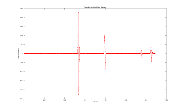
Immediately following the birds-eye mapping of the input image, the output is convolved with a filter designed to locate strips of high intensity pixels on a dark background. The width of the kernel is 8 pixels, which relates to the width of the lines that appear in the birds-eye image. The height is set to 16 which relates to the size of the dashed lane markings which appear in the image. As the birds-eye image is physically related to the height, pitch etc. of the camera, the width at which lanes appear in this image is intrinsically related to the physical measurement on the road. The width and height of the kernel may need to be updated when operating the lane detection system in different countries.

滤波器内核的输出如下所示,使用Jet Colormap突出强度的差异。因为过滤器内核是一般的垂直定向高斯衍生物,所以来自许多不同区域存在一些响应。然而,对于存在车道标记的位置,存在具有强的正响应,其在强的负响应旁边,这在柱上一致。滤波器输出的该特性用于检测算法的下一阶段来定位有效车道候选。

Lane Candidate Generation
在用高斯衍生内核卷积之后,执行输出的子区域处理,以便找到存在车道标记的坐标。每个区域由18行组成,具有ping-pong内存方案,以确保数据可以连续流通过子系统流。
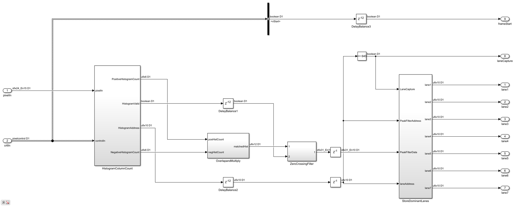
直方图列计数
Firstly, HistogramColumnCount counts the number of thresholded pixels in each column over the 18 line region. A high column count indicates that a lane is likely present in the region. This count is performed for both the positive and the negative thresholded images. The positive histogram counts are offset to account for the kernel width. Lane candidates occur where the positive count and negative counts are both high. This exploits the previously noted property of the convolution output where positive tracks appear next to negative tracks.
在内部,列计数直方图生成选择18行区域的控制信令,计算列直方图,并在准备就绪时输出结果。乒乓缓冲方案是允许一个直方图在下一步写入时阅读。
重叠和乘法
如上所述,当鸟瞰图像中存在车道时,卷积结果将产生位于高强度负输出条旁边的高强度正输出条。正柱数计数直方图定位了这样的区域。为了放大这些位置,正计数输出延迟了8个时钟周期(与内核宽度相关的内部参数),并且正数和负计数乘以一起。这可以放大正数和负计数的柱,并最大限度地减少在正面和负数之间存在分歧的区域。该设计是流水线,以确保高吞吐量操作。

Zero Crossing Filter
At the output of the Overlap and Multiply subsystem, peaks appear where there are lane markings present. A peak detection algorithm determines the columns where lane markings are present. Because the SNR is relatively high in the data, this example uses a simple FIR filtering operation followed by zero crossing detection. The Zero Crossing Filter is implemented using the Discrete FIR Filter block from DSP System Toolbox™. It is pipelined for high-throughput operation.
Store Dominant Lanes
然后将零交叉滤波器输出传递到商店主导车道子系统中。该子系统具有7个条目的最大内存,并且每次达到新的18行时都会重置。因此,对于每个子区域7,产生潜在车道候选。在该子系统中,零交叉滤波器输出流通过,并检查势零点。如果发生过零交叉,则采取在过零之前的地址与零交叉后的地址之间的差异以获得峰值的尺寸的测量。子系统将零交叉位置存储具有最高幅度。

计算自我车道
车道检测子系统输出7个最活力的车道标记。在许多应用中,我们对包含车辆驾驶的车道的车道标记最感兴趣。通过计算设计的硬件方面所谓的“自助式通道”,我们可以通过向处理器发送2个轿厢而不是7,减少硬件和软件之间的内存带宽。自我车道计算分为两个子系统。第一个PasSegolane子系统假定图像的中心列对应于车道的中间,当车辆在车道边界内正确操作时。因此,假设最接近中心的车道候选者作为自我车道。异常删除子系统维持与车道标记到中心坐标的距离的平均宽度。拒绝不在电流宽度的公差范围内的车道标记。执行早期拒绝车道标记,在稍后在设计中进行曲线时提供更好的结果。
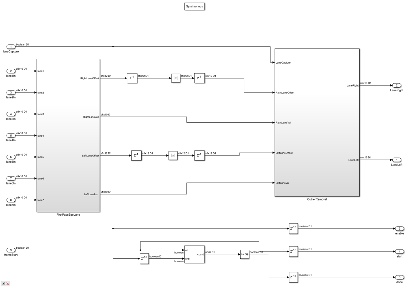
控制界面
Finally, the computed ego lanes are sent to the CtrlInterface MATLAB function subsystem. This state machine uses the four control signal inputs - enable, hwStart, hwDone, and swStart to determine when to start buffering, accept new lane coordinate into the 40x1 buffer and finally indicate to the software that all 40 lane coordinates have been buffered and so the lane fitting and overlay can be performed. The dataReady signal ensures that software will not attempt lane fitting until all 40 coordinates have been buffered, while the swStart signal ensures that the current set of 40 coordinates will be held until lane fitting is completed.
Software Lane Fit and Overlay
该detected ego-lanes are then passed to the SW Lane Fit and Overlay subsystem, where robust curve fitting and overlay is performed. Recall that the birds-eye output is produced once every two frames or so rather than on every consecutive frame. The curve fitting and overlay is therefore placed in an enabled subsystem, which is only enabled when new ego lanes are produced.
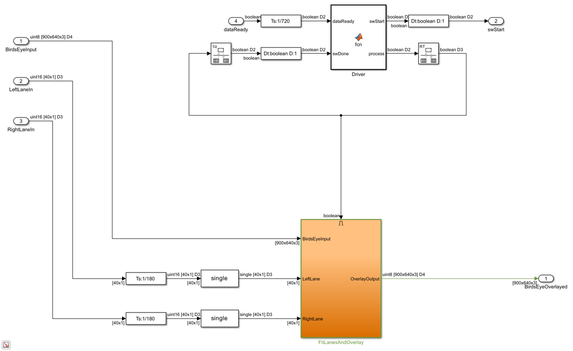
Driver
该Driver MATLAB Function subsystem controls the synchronization between hardware and software. Initially it is in a polling state, where it samples the dataReady input at regular intervals per frame to determine when hardware has buffered a full [40x1] vector of lane coordinates. Once this occurs, it transitions into software processing state where swStart and process outputs are held high. The Driver remains in the software processing state until swDone input is high. Seeing as the process output loops back to swDone input with a rate transition block in between, there is effectively a constant time budget specified for the FitLanesandOverlay subsystem to perform the fitting and overlay. When swDone is high, the Driver will transition into a synchronization state, where swStart is held low to indicate to hardware that processing is complete. The synchronization between software and hardware is such that hardware will hold the [40x1] vector of lane coordinates until the swStart signal transitions back to low. When this occurs, dataReady output of hardware will then transition back to low.
适合车道和覆盖物
驱动程序启用拟合通道和覆盖子系统。它执行所需的必要算术,以便将多项式拟合到在输入的通道接收的车道坐标数据上,然后将装配的车道和车道坐标绘制到鸟瞰图像上。
适合车道
该适合车道subsystem runs a RANSAC based line-fitting routine on the generated lane candidates. RANSAC is an iterative algorithm which builds up a table of inliers based on a distance measure between the proposed curve, and the input data. At the output of this subsystem, there is a [3x1] vector which specifies the polynomial coefficients found by the RANSAC routine.
Overlay Lane Markings
该Overlay Lane Markings subsystem performs image visualization operations. It overlays the ego lanes and curves found by the lane-fitting routine.

模拟结果
该模型包括在仿真结果的输出时显示的两个视频显示。该Birdseye.display shows the output in the warped perspective after lane candidates have been overlaid, polynomial fitting has been performed and the resulting polynomial overlaid onto the image. The原始overlaydisplay shows theBirdseye.产出扭转回原始角度。
由于该模型中使用的大型框架尺寸,模拟可能需要相对较长的时间才能完成。如果您有HDL Verifer™许可证,可以通过在循环(TM)中使用FPGA直接运行HDL Lane检测器子系统来加速仿真速度。

HDL代码生成
要检查和生成此示例中引用的HDL代码,必须具有HDL Coder™许可证。
要生成HDL代码,请使用以下命令。
makehdl('lanedetectionhdl / hdllanedetector')
要生成测试台,请使用以下命令。请注意,由于数据大小大,测试台代生成需要很长时间。在生成测试台之前,您可能希望减少模拟时间。
makehdltb('lanedetectionhdl / hdllanedetector')
For faster test bench simulation, you can generate a SystemVerilog DPIC test bench using the following command.
makehdltb('lanedetectionhdl / hdllanedetector','GenerateSVDPITestBench','ModelSim')
结论
这个示例提供了洞察challenges of designing ADAS systems in general, with particular emphasis paid to the acceleration of critical parts of the design in hardware.
参考资料
[1] R.K.Satzoda和Mohan M. Trivei,“基于视觉的车道分析:探讨了嵌入式实现的问题和方法”,2013年计算机视觉和模式识别。
[2] Video from Caltech Lanes Dataset - Mohamed Aly, "Real time Detection of Lane Markers in Urban Streets", 2008 IEEE Intelligent Vehicles Symposium - used with permission.
相关话题
选择一个网站
Choose a web site to get translated content where available and see local events and offers. Based on your location, we recommend that you select:.
Select网站您还可以从以下列表中选择一个网站: