 Cleve’s Corner: Cleve Moler on Mathematics and Computing
 Loren on the Art of MATLAB
 Steve on Image Processing with MATLAB
 Guy on Simulink
 Deep Learning
 Developer Zone
 Stuart’s MATLAB Videos
 Behind the Headlines
 File Exchange Pick of the Week
 Hans on IoT
 Student Lounge
 Startups, Accelerators, & Entrepreneurs
 MATLAB Community
 MATLAB ユーザーコミュニティー
Internal Combustion Engine Ignition Control Example – Part 1
This post introduces an example project I recently submitted to MATLAB Central:Four-Cylinder Engine Ignition Control Simulation
This project was made in collaboration with Isaac Hisahiro Ito at Toyota Motor North America R&D. Inside this project, you will find:
- Simulation of a 4-cylinder engine implemented using theSimscape Language
- Design of the engine model using theSymbolic Math toolbox
- Drivetrain implemented usingSimscape Driveline
- Controller implemented using anexport-function style model, allowing the code generated usingEmbedded Coderto be integrated with an external environment and real-time OS scheduler of an Engine Electronic Control Unit (ECU)
- Simulation of the real-time OS scheduler usingStateflow
- Simulation of the microcontroller's hardware timers usingSimEvents
This project is for educational purposes, with the objective of demonstrating how the listed products can be used together.
在今天的文章中,我描述了建模(t)he engine and drivetrain. I will follow up next week with a post describing the controller implementation.
Overview
This image illustrates the succession of events in this project.
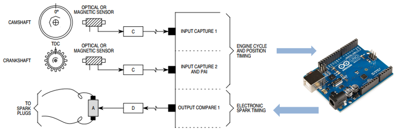
- The engine crankshaft is equipped with a toothed wheel. In this case, the teeth are equally spaced every 10 degrees, with one missing tooth.
- When the crankshaft rotates, the teeth pass in front of a sensor that triggers an interrupt, executing code on the ECU.
- The code computes the position and speed of the engine and determines when the next cylinder should fire.
- The code sets a hardware timer that will fire the appropriate spark plug at the appropriate time.
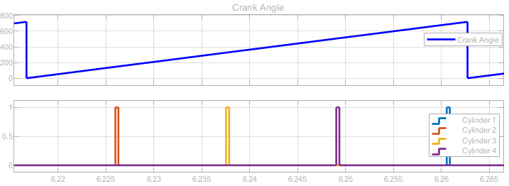
The next plot shows when the spark plugs are fired for each cylinder during one combustion cycle.
开始
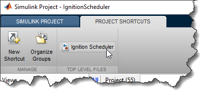
For convenience, all the files involved in the project are included in a Simulink Project. When you open the project, a shortcut to the main model appears:
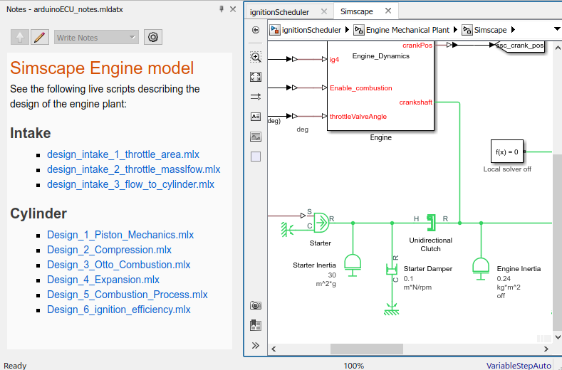
Here is what the main model looks like.
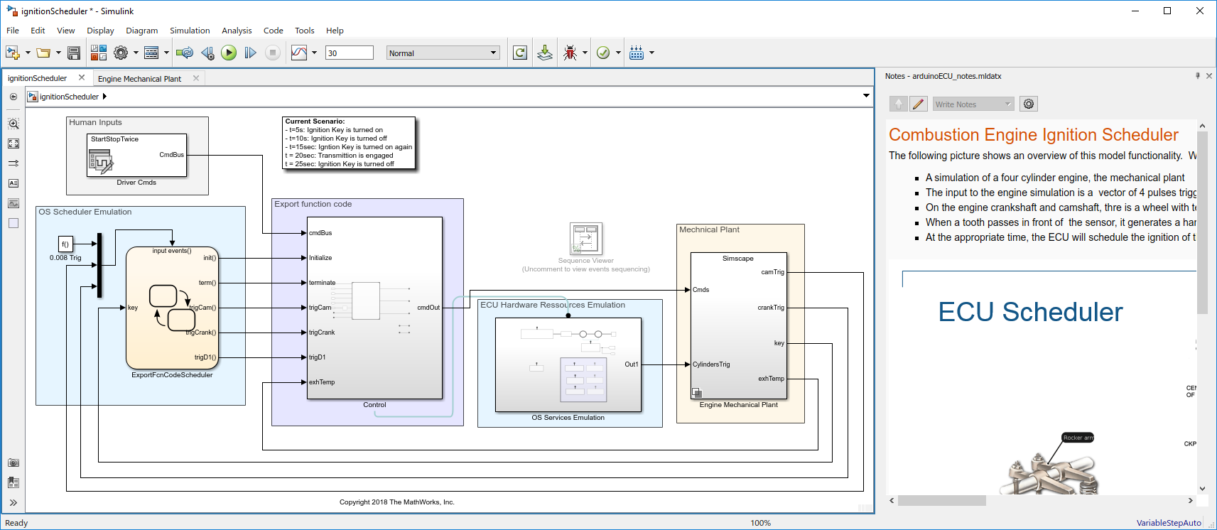
Click image to enlarge
To document what each Subsystem is doing, I useNotes. Notes are a convenient way to add rich text, equations, and images to a model. You can open and close the Notes from the View menu or by hitting Ctrl+Shift+N. In case you had not noticed, you can click and drag the title bar of the Notes to move it to the top, bottom, left or right. You can even undock it from the canvas.
Engine Design using the Symbolic Math Toolbox
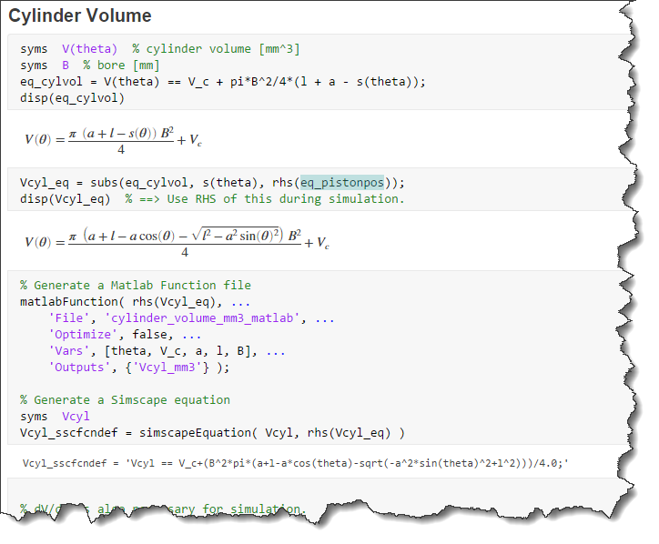
Inside the Subsystem containing the engine model, you will see that the Notes provide hyperlinks to a series of MATLAB LiveScripts that my collaborator Isaac created to design the engine model:
In those files, Isaac generated MATLAB functions and Simscape equations directly from the Symbolic Math Toolbox. Here is an example computing the cylinder volume as a function of the crank angle.
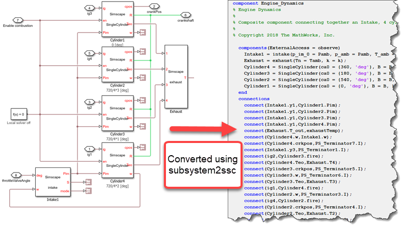
Four-Cylinder Engine Implemented using Simscape Language
To incorporate his design in Simulink, Isaac used the Simscape language. UsingMode Chart Modeling, he implemented equations for each phase of the combustion cycle: intake, compression, expansion and exhaust.
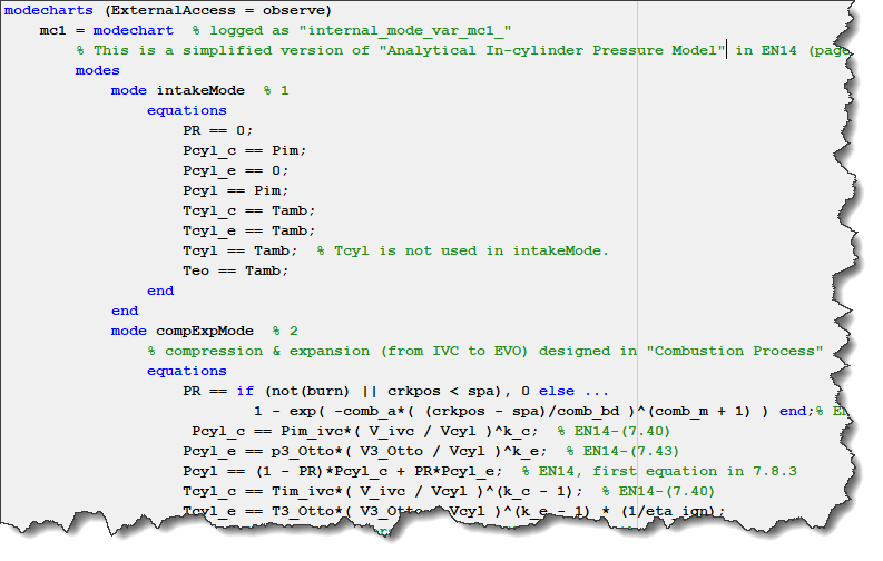
In addition to a cylinder component, Isaac also implemented an intake component, allowing to control the airflow going in the engine using a throttle valve, and an exhaust component.
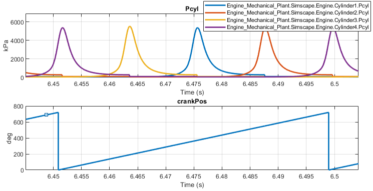
Here is what the pressure in the cylinders looks like over the course of a single combustion cycle..
To assemble the engine, we connected the intake, the four cylinders and the exhaust components together using physical connections inside a Subsystem. I then used the new R2018b functionsubsystem2sscto convert this Subsystem into aSimscape composite component, which we could then include in the model using theSimscape Componentblock. This enables us to have all the engine parameters in one convenient dialog.
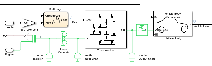
Drivetrain Modeling using Simscape Driveline
To add a load for the engine, I used Simscape Driveline blocks likeTorque Converter,ClutchandPlanetary Gearto model the drivetrain. I recommend looking at theComplete Vehicle Model examplefor a well documented similar implementation.
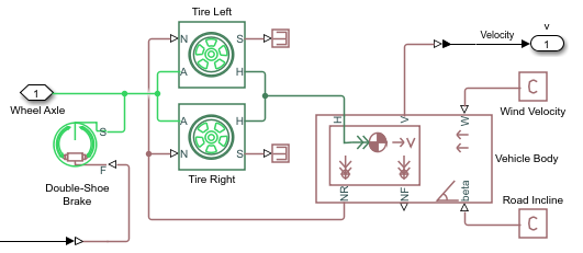
Vehicle Body
For the Vehicle body, I decided to implement two versions usingVariant Subsystems
Because Isaac implemented the engine model using Simscape, I made the first implementation using Simscape Driveline:
For the second implementation, I thought it would be a good opportunity to showcase the existence of the new product released in R2016b,Powertrain Blockset. This product does not (yet!) have an engine model suitable for this application, but it includes a library of components for simulating engine subsystems, transmission assemblies, traction motors, battery packs, and so on.
Here is how I interfaced theVehicle Body 1DOF Longitudinalto the rest of the Simscape network:
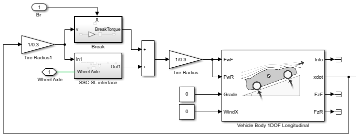
I recommend that you take a look at thelibrary of fully assembled reference application modelsof automotive powertrains, including gasoline, diesel, hybrid, and electric systems included with the Powertrain Blockset.
Now it's your turn
In my next blog post, I will describe the remaining model architecture.
In the meantime, I would love to hear from you. Post your comments or questions below.


Comments
To leave a comment, please clickhereto sign in to your MathWorks Account or create a new one.