LTE下行链路通道估计和均衡
This example shows how to use the LTE Toolbox™ to create a frame worth of data, pass it through a fading channel and perform channel estimation and equalization. Two figures are created illustrating the received and equalized frame.
Introduction
此示例显示了如何使用LTE工具箱中的函数创建简单的发送器通道接收器模拟。该示例在一个天线端口上生成了一个数据框架。由于在此示例中没有创建传输通道,因此数据是随机位,QPSK调制并映射到子帧中的每个符号。创建并映射到子框架并映射到细胞特定的参考信号以及主要和次要同步信号。单独生成10个子帧以创建帧。框架是OFDM调制的,通过扩展的车辆A型号(EVA5)褪色通道,添加并解调了添加的白色高斯噪声。使用通道和噪声估计的MMSE均衡化,最后绘制了接收和均衡资源网格。
细胞范围的设置
The cell-wide settings are specified in a structureenb。A number of the functions used in this example require a subset of the settings specified below. In this example only one transmit antenna is used.
enb.ndlrb = 15;资源块数量的%enb.CellRefP = 1;%一个传输天线端口enb.NCellID = 10;% Cell IDenb.CyclicPrefix ='普通的';% Normal cyclic prefixenb.duplexmode ='fdd';% FDD
snrConfiguration
操作SNR是按值在分贝中配置的snrdBwhich is also converted into a linear SNR.
snrdb = 22;DB中的%所需SNRsnr=10^(SNRdB/20);%线性SNRrng('默认');%配置随机数生成器
频道模型配置
使用结构配置通道模型。在此示例中,使用具有扩展车辆A(EVA)延迟轮廓和120Hz多普勒频率的褪色通道。设置了这些参数以及MIMO相关性和其他通道模型特定参数。
cfg.seed = 1;% Channel seedcfg。nrxAnts = 1;%1接收天线cfg。DelayProfile ='EVA';% EVA delay spreadcfg.dopplerfreq = 120;%120Hz多普勒频率cfg.mimocrolation ='低的';% Low (no) MIMO correlationcfg。InitTime = 0;% Initialize at time zerocfg。nTerms = 16;褪色模型中使用的%振荡器cfg。ModelType ='GMEDS';% Rayleigh fading model typecfg.initphase ='Random';%随机初始阶段cfg。normalizePathGains ='上';%归一化延迟轮廓功率cfg。normalizeTxAnts ='上';% Normalize for transmit antennas
Channel Estimator Configuration
A user defined window is used to average pilot symbols to reduce the effect of noise. The averaging window size is configured in terms of resource elements (REs), in time and frequency. A conservative 9-by-9 window is used in this example as an EVA delay profile and 120Hz Doppler frequency cause the channel changes quickly over time and frequency. A 9-by-9 window includes the 4 pilots immediately surrounding the pilot of interest when averaging. Selecting an averaging window is discussed inChannel Estimation。
cec.pilotaverage ='UserDefined';% Pilot averaging methodcec.freqwindow = 9;% Frequency averaging window in REsCEC.TimeWindow = 9;% Time averaging window in REs
Interpolation is performed by the channel estimator between pilot estimates to create a channel estimate for all REs. To improve the estimate multiple subframes can be used when interpolating. An interpolation window of 3 subframes with a centered interpolation window uses pilot estimates from 3 consecutive subframes to estimate the center subframe.
CEC。InterpType ='Cubic';%立方插值CEC。InterpWinSize = 3;%插值最多3个子帧% 同时CEC。InterpWindow =“居中”;%插值窗法方法
副帧资源网格大小
In this example it is useful to have access to the subframe resource grid dimensions. These are determined usinglteDLResourceGridSize。This function returns an array containing the number of subcarriers, number of OFDM symbols and number of transmit antenna ports in that order.
gridsize = ltedlresourcegridsize(enb);k =栅格(1);% Number of subcarriersL = gridsize(2);% Number of OFDM symbols in one subframeP = gridsize(3);% Number of transmit antenna ports
Transmit Resource Grid
An empty resource gridtxGridis created which will be populated with subframes.
txGrid = [];
有效载荷数据生成
因为没有传输通道中使用这个例子the data sent over the channel will be random QPSK modulated symbols. A subframe worth of symbols is created so a symbol can be mapped to every resource element. Other signals required for transmission and reception will overwrite these symbols in the resource grid.
所需位数的%是资源网格的尺寸(k*l*p)*位数每个符号%(qpsk 2)numberOfBits = K*L*P*2;% Create random bit streaminputBits = randi([0 1], numberOfBits, 1);% Modulate input bitsinputSym = lteSymbolModulate(inputBits,'QPSK');
Frame Generation
将通过在循环中生成各个子帧并将每个创建的子框架附加到上一个子帧中来创建帧。附加子帧的集合包含txGrid。This appending is repeated ten times to create a frame. When the OFDM modulated time domain waveform is passed through a channel the waveform will experience a delay. To avoid any samples being missed due to this delay an extra subframe is generated, therefore 11 subframes are generated in total. For each subframe the Cell-Specific Reference Signal (Cell RS) is added. The Primary Synchronization Signal (PSS) and Secondary Synchronization Signal (SSS) are also added. Note that these synchronization signals only occur in subframes 0 and 5, but the LTE Toolbox takes care of generating empty signals and indices in the other subframes so that the calling syntax here can be completely uniform across the subframes.
框架中所有子帧的%forsf = 0:10% Set subframe numberenb.nsubframe = mod(sf,10);%生成空子帧subframe = lteDLResourceGrid(enb);%地图输入符号到网格子帧(:) = inputsym;% Generate synchronizing signalsPSSSYM = LTEPSS(ENB);ssssym = ltesss(enb);pssind = ltepssindices(enb);SSSIND = LTESSSINDICES(ENB);% Map synchronizing signals to the gridsubframe(pssInd) = pssSym; subframe(sssInd) = sssSym;% Generate cell specific reference signal symbols and indicescellRsSym = lteCellRS(enb); cellRsInd = lteCellRSIndices(enb);% Map cell specific reference signal to grid子帧(CellRsind)= CellRssym;% Append subframe to grid to be transmittedtxgrid = [txgrid子帧];%#okend
OFDM Modulation
为了将频域OFDM符号转换为时域,需要调制OFDM。这是使用lteOFDMModulate。The function returns two values; a matrixtxWaveformand a structure信息containing the sampling rate.txWaveform是最终的时域波形。每列包含每个天线端口的时域信号。在此示例中,由于仅使用一个天线端口,因此仅返回一列。信息。samplingRateis the sampling rate at which the time domain waveform was created. This value is required by the channel model.
[txWaveform,info] = lteOFDMModulate(enb,txGrid); txGrid = txGrid(:,1:140);
褪色频道
The time domain waveform is passed through the channel model (lteFadingChannel)由结构配置CFG。The channel model requires the sampling rate of the time domain waveform so the parametercfg。samplingRate设置为返回的值lteOFDMModulate。The waveform generated by the channel model function contains one column per receive antenna. In this example one receive antenna is used, therefore the returned waveform has one column.
cfg。samplingRate = info.SamplingRate;% Pass data through the fading channel modelrxwaveform = ltefadingChannel(CFG,TXWAVEFORM);
Additive Noise
SNR由
在哪里
是感兴趣的信号的能量
是噪声力量。FFT将扩大OFDM解调之前添加的噪声。因此,要使接收器处的SNR归一化(OFDM解调后)必须缩放噪声。放大是FFT大小的平方根。FFT的大小可以从时域波形的采样率(信息。samplingRate) and the subcarrier spacing (15 kHz). The power of the noise to be added can be scaled so that
and
are normalized after the OFDM demodulation to achieve the desired SNR (snrdB).
% Calculate noise gainn0=1/(sqrt(2.0*enb.CellRefP*double(info.Nfft))*SNR);% Create additive white Gaussian noise噪声= n0*复杂(randn(size(rxwaveform))),randn(size(rxwaveform)));%在接收到的时域波形中添加噪音rxWaveform = rxWaveform +noise;
同步
使用接收到的时间域信号中的通道引起的偏移是使用的lteDLFrameOffset。此功能返回值offsetwhich indicates how many samples the waveform has been delayed. The offset is considered identical for waveforms received on all antennas. The received time domain waveform can then be manipulated to remove the delay usingoffset。
offset = lteDLFrameOffset(enb,rxWaveform); rxWaveform = rxWaveform(1+offset:end,:);
OFDM解调
时域波形经历了OFDM解调以将其转换为频域并重新创建资源网格。这是使用lteOFDMDemodulate。The resulting grid is a 3-dimensional matrix. The number of rows represents the number of subcarriers. The number of columns equals the number of OFDM symbols in a subframe. The number of subcarriers and symbols is the same for the returned grid from OFDM demodulation as the grid passed intolteOFDMModulate。网格中的平面数(第三维)对应于接收天线的数量。
rxgrid=lteOFDMDemodulate(enb,rxWaveform);
Channel Estimation
To create an estimation of the channel over the duration of the transmitted resource gridltedlchanneLestimate用来。通道估计功能由结构配置CEC。ltedlchanneLestimate假设资源网格中的第一个子帧是子帧号码enb.NSubframeand therefore the subframe number must be set prior to calling the function. In this example the whole received frame will be estimated in one call and the first subframe within the frame is subframe number 0. The function returns a 4-D array of complex weights which the channel applies to each resource element in the transmitted grid for each possible transmit and receive antenna combination. The possible combinations are based upon the eNodeB configurationenband the number of receive antennas (determined by the size of the received resource grid). The 1st dimension is the subcarrier, the 2nd dimension is the OFDM symbol, the 3rd dimension is the receive antenna and the 4th dimension is the transmit antenna. In this example one transmit and one receive antenna is used therefore the size ofestChannel是180 x-140-by-1-by-1。
enb.NSubframe = 0; [estChannel, noiseEst] = lteDLChannelEstimate(enb,cec,rxGrid);
MMSE均衡
通道对接收资源网格的影响使用lteEqualizeMMSE。此功能使用通道的估计值estChanneland noise最噪音to equalize the received resource gridrxgrid。The function returnseqgridwhich is the equalized grid. The dimensions of the equalized grid are the same as the original transmitted grid (txGrid)OFDM调制之前。
eqgrid=lteEqualizeMMSE(rxGrid, estChannel, noiseEst);
分析
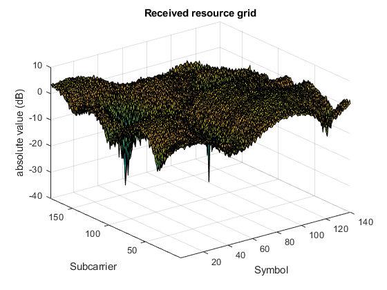
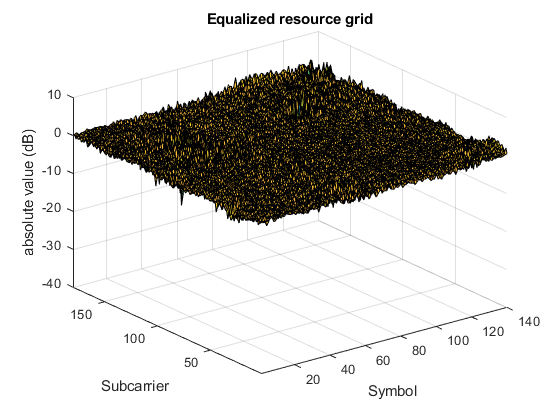
The received resource grid is compared with the equalized resource grid. The error between the transmitted and equalized grid and transmitted and received grids are calculated. This creates two matrices (the same size as the resource arrays) which contain the error for each symbol. To allow easy inspection the received and equalized grids are plotted on a logarithmic scale using冲浪withinhdownlinkestimationequalizationResults.m。These diagrams show that performing channel equalization drastically reduces the error in the received resource grid.
% Calculate error between transmitted and equalized grideqerror = txgrid -eqgrid;rxError = txGrid -rxGrid;% Compute EVM across all input values% EVM of pre-equalized receive signalevm = comm.evm;evm.AveragingDirensions = [1 2];preequalishisevm = evm(txgrid,rxgrid);fprintf('Percentage RMS EVM of Pre-Equalized signal: %0.3f%%\n',,,,...预先定位);
预先平等信号的RMS EVM百分比:124.133%
% EVM of post-equalized receive signalExequalistionEvm = EVM(TXGRID,EQGRID);fprintf('Percentage RMS EVM of Post-Equalized signal: %0.3f%%\n',,,,...postEqualisedEVM);
公平后信号的RMS百分比:15.598%
%绘制接收和均衡的资源网格hdownlinkestimatimatimationequalizationResults(rxgrid,eqgrid);
附录
此示例使用辅助功能:
You can also select a web site from the following list:
Americas
- AméricaLatina(Español)
- Canada(English)
- United States(English)