Reporting of Channel Quality Indicator (CQI) Conformance Test
This example demonstrates how to measure the Channel Quality Indicator (CQI) reporting performance using the LTE Toolbox™ under conformance test conditions as defined in TS36.101 Section 9.3.2.1.1.
Introduction
This example highlights the use of thelteCQISelectfunction which provides estimation of the CQI. The performance of the CQI estimation is also tested. This example provides a testbench which shows that the LTE Toolbox can satisfy the CQI reporting performance test defined in TS36.101 Section 9.3.2.1.1 [1]. The performance requirements of the test are as follows:
医院药学部医院药学部的指数不是一组{值- 1,值CQI + 1} shall be reported at least 20% of the time;
the ratio of the throughput obtained when transmitting the transport format indicated by each reported wideband CQI index and that obtained when transmitting a fixed transport format configured according to the wideband CQI median shall be >= 1.05;
when transmitting the transport format indicated by each reported wideband CQI index, the average BLER for the indicated transport formats shall be greater than or equal to 0.02.
This example tests that these requirements are met.
Simulation Configuration
The example is executed for a simulation length of 10 frames at an SNR of 6.0dB. A large number ofNFramesshould be used to produce meaningful results.
NFrames = 10; SNRdB = 6.0;
eNodeB Configuration
eNodeB settings are specified in a structureenb. This includes a substructurePDSCHto configure the PDSCH according to the conformance test requirements: HARQ is disabled by setting the RV sequence to zero and the value ofCSIModeis configured according to TS36.101 Table 9.3.2.1.1-1 [1].
enb = struct('RC','R.3');% Set up parameters of RMC R.3enb = lteRMCDL(enb); enb.CFI = 3;% Reconfigure Control Format Indicatorenb.OCNGPDSCHEnable ='On';% Enable OCNG for unallocated PDSCH REsenb.TotSubframes = 1;% Reconfigure for a single subframeenb.PDSCH.RVSeq = 0;% Disable HARQenb.PDSCH.CSIMode ='PUCCH 1-0';% Configure the CSI reporting modeenb.PDSCH.CSI ='On';% CSI scaling of soft bits
Propagation Channel Model Configuration
The structure,channel, contains the channel model configuration parameters.
channel.Seed = 10;% Channel seedchannel.NRxAnts = 2;% 2 receive antennaschannel.DelayProfile ='EPA';% Delay profilechannel.DopplerFreq = 5.0;% Doppler frequencychannel.MIMOCorrelation ='High';% Multi-antenna correlationchannel.ModelType =“GMEDS';% Rayleigh fading model typechannel.NormalizeTxAnts ='On';% Normalize for transmit antennaschannel.NormalizePathGains ='On';% Normalize delay profile powerchannel.InitPhase ='Random';% Random initial phaseschannel.NTerms = 16;% Oscillators used in fading model% Set channel model sampling rateofdmInfo = lteOFDMInfo(enb); channel.SamplingRate = ofdmInfo.SamplingRate;
Channel Estimator Configuration
The channel estimator is configured with a structurecec. The variableperfectChanEstimatorcontrols channel estimator behavior. Valid values aretrueorfalse. When set totruea perfect channel estimator is used otherwise an imperfect estimate of the channel is used, based on the values of received pilot signals. In this example, we enable the perfect channel estimator.
% Configure channel estimatorcec.PilotAverage ='UserDefined';% Type of pilot symbol averagingcec.FreqWindow = 9;% Frequency window size in REscec.TimeWindow = 9;% Time window size in REscec.InterpType ='Cubic';% 2D interpolation typecec.InterpWindow ='Centered';% Interpolation window typecec.InterpWinSize = 1;% Interpolation window size% Channel estimator behaviorperfectChanEstimator = true;
Set CQI Delay
Set the CQI delay in subframes. This is the delay in a CQI being passed from UE to eNodeB as defined in TS36.101 Table 9.3.2.1.1-1 [1]. Note that the feedback of the CQI is assumed to be perfect, with the values being fed back in a buffer rather than being fed back in an uplink transmission.
cqiDelay = 8;% subframes
System Processing
The main processing is split into two phases, configured via thecqiConfigloop variable. These phases implement the two measurements required in the performance test defined in TS36.101 Section 9.3.2.1.1 [1]:
UE reported CQI.The first phase (cqiConfig=1) performs PDSCH transmission and reception where the Modulation and Coding Scheme (MCS) is selected on the basis of the UE reported CQI, with the reported CQI being updated every 2 subframes and fed back with a delay of 8 subframes. The final throughput, BLER and median CQI are recorded, and the BLER (measuredBLER) and deviation from the median CQI (measuredAlpha, in percent) are checked against the specified performance requirements.
Median CQI.In the second phase (cqiConfig=2), PDSCH transmission and reception are performed using the median CQI (medianCQI) determined in the first phase. The final throughput is recorded and the throughput ratio (measuredGamma) between using the UE reported CQI phase and the median CQI phase is reported and checked against the specified performance requirement.
The processing is performed on a subframe by subframe basis using the following steps:
Select CQI.医院药学部问题报道,医院药学部当前is read from the oldest value in the CQI buffer
cqiBuffer; for median CQI, the CQI is always set tomedianCQI(this is achieved by filling the CQI buffer with the median CQI value and the buffer will not be updated).
Select MCS according to CQI.The Modulation and Coding Scheme (MCS) index corresponding to the CQI is selected by means of a lookup table defined by TS36.101 Table A.4-1 CSI RMC RC.1 FDD (MCS.1).
Determine Transport Block Size and modulation order.The MCS index is passed to the
lteMCSfunction which calculates the corresponding Transport Block Size (TBS) index and modulation order; thelteTBSfunction is then used to calculate the TBS from the TBS index and the number of resource blocks allocated to the PDSCH.
Transmit and receive waveform.Transport block data is generated and passed to
lteRMCDLToolto create a transmitted downlink waveform. This waveform is then passed through a fading channel and AWGN noise is added. The received signal is synchronized and OFDM demodulated and channel estimation is performed.
Measure PDSCH throughput.The PDSCH and DL-SCH are decoded and the CRC pass/fail is recorded to determine the data throughput.
Update CQI.If a CQI update is scheduled in this subframe, use the channel estimate to update the CQI with the
lteCQISelectfunction. The updated CQI value is recorded in the CQI buffer. If a CQI update is not scheduled in this subframe, the previous CQI value is reused.
% Initialize variables used for results recordingCQIReport = [];% reported CQI valuesSINRReport = [];% corresponding SINR valuesxaxis = [];% corresponding subframe numbers% For each CQI configuration (UE reported and median):forcqiConfig = 1:2if(cqiConfig==1) cqiConfigStr ='UE reported';elsecqiConfigStr ='median';endfprintf('\nSimulating with %s CQI at %gdB SNR for %d Frame(s)\n',...cqiConfigStr,SNRdB,NFrames);% Initialize CQI values: for UE reported, set to all ones; for median,% set to the median of the CQI values for the UE reported runif(cqiConfig==1) cqiBuffer = ones(1,cqiDelay);elsecqiBuffer = ones(1,cqiDelay)*medianCQI;end% Initialize variablesrng('default');% Default random number generator seedtotalCRC = [];% CRC values, used for throughput calculationtotalTBS = [];% TBS values, used for throughput calculationoffsets = 0;% Initialize frame offset value% For each subframe:forsubframeNo = 0:(NFrames*10-1)% Update subframe numberenb.NSubframe = mod(subframeNo,10);% Select CQI, reading the oldest value from the CQI buffercqiPtr = mod(subframeNo,cqiDelay); CQI = cqiBuffer(cqiPtr+1);% Select MCS according to CQI using TS36.101 Table A.4-1 CSI RMC% RC.1 FDD (MCS.1), which defines the relationship between CQI% indices and MCS indicesIMCSTable = [-1 0 0 2 4 6 8 11 13 16 18 21 23 25 27 27]; IMCS = IMCSTable(CQI+1);% Determine TBS and modulation order[ITBS,modulation] = lteMCS(IMCS); enb.PDSCH.Modulation = {modulation};if(mod(enb.NSubframe,5)==0) TBS = 0;elseTBS = double(lteTBS(size(enb.PDSCH.PRBSet,1),ITBS));endenb.PDSCH.TrBlkSizes(enb.NSubframe+1) = TBS;% Determine if a CQI update is required in this subframe, according% to reporting periodicity N_pd = 2ms and configuration index% cqi-pmi-ConfigurationIndex = 1 from TS36.101 Table 9.3.2.1.1-1cqiPeriod = 2;% periodicity N_pdcqiOffset = 1;% offset deriving from cqi-pmi-ConfigurationIndexcqiUpdate = (mod(subframeNo,cqiPeriod)==cqiOffset);% Establish if this subframe actually needs executed for PDSCH% reception, CQI estimation or initial timing offset estimation:if((TBS~=0 && subframeNo>=(cqiDelay+cqiOffset)) ||...(cqiConfig==1 && cqiUpdate) || subframeNo==0)% Generate random bits for the subframedata = randi([0 1],TBS,1);% Create OFDM resource grid containing RMC transmission and% perform OFDM modulation.txWaveform = lteRMCDLTool(enb,data);% The initialization time for channel modeling is set each% subframe to simulate a continuously varying channelchannel.InitTime = subframeNo/1000;% Pass data through the fading channel model.% An additional 25 samples are added to the end of the% waveform. These are to cover the range of delays expected% from the channel modeling (a combination of implementation% delay and channel delay spread)rxWaveform = lteFadingChannel(channel,...[txWaveform ; zeros(25,size(txWaveform,2))]);% Calculate noise gain including compensation for downlink% power allocationSNR = 10^((SNRdB-enb.PDSCH.Rho)/20);% Normalize noise power to take account of sampling rate, which% is a function of the IFFT size used in OFDM modulation, and% the number of antennasN0 = 1/(sqrt(2.0*enb.CellRefP*double(ofdmInfo.Nfft))*SNR);% Create additive white Gaussian noisenoise = N0*complex(randn(size(rxWaveform)),...randn(size(rxWaveform)));%添加情况下接收到的时域波形rxWaveform = rxWaveform + noise;% Perform synchronization% An offset within the range of delays expected from the% channel modeling (a combination of implementation delay and% channel delay spread) indicates successif(mod(subframeNo,10)==0) offset = lteDLFrameOffset(enb,rxWaveform);if(offset > 25) offset = offsets(end);endoffsets = [offsets offset];%#okendrxWaveform = rxWaveform(1+offset:end,:);% Perform OFDM demodulation on the received data to create% the received resource gridrxGrid = lteOFDMDemodulate(enb,rxWaveform);% Channel estimationif(perfectChanEstimator) chEstGrid =...lteDLPerfectChannelEstimate(enb,channel,offset); n = lteOFDMDemodulate(enb,noise(1+offset:end,:)); noiseEst = var(reshape(n,numel(n),1));else[chEstGrid,noiseEst] =...lteDLChannelEstimate(enb,enb.PDSCH,...cec、rxGrid);%#ok end% If this subframe requires PDSCH reception:if(TBS~=0 && subframeNo>=(cqiDelay+cqiOffset))% Decode the PDSCHind = ltePDSCHIndices(enb,enb.PDSCH,enb.PDSCH.PRBSet); pdschRx = lteExtractResources(ind,rxGrid) *...(10^(-enb.PDSCH.Rho/20)); pdschChEst = lteExtractResources(ind,chEstGrid); [rxBits,rxSymbols] = ltePDSCHDecode(enb,enb.PDSCH,...pdschRx,pdschChEst,noiseEst);% Decode the DL-SCH[decbits,crc] = lteDLSCHDecode(enb,enb.PDSCH,TBS,rxBits);% Record the CRC and TBS values for final throughput% calculationtotalCRC = [totalCRC crc];%#ok totalTBS = [totalTBS TBS];%#ok end% Update CQI:if(cqiConfig==1 && cqiUpdate)% Perform CQI selection[thisCQI,thisSINR] =...lteCQISelect(enb,enb.PDSCH,chEstGrid,noiseEst);% Feed the CQI value back to UE (in a buffer)cqiBuffer(cqiPtr+1) = thisCQI;% Record values for plottingCQIReport = [CQIReport thisCQI];%#ok SINRReport = [SINRReport thisSINR];%#ok xaxis = [xaxis subframeNo];%#ok endend% For subframes where CQI was not updated, re-use the previous% value in the bufferif(cqiConfig==1 && ~cqiUpdate) cqiBuffer(cqiPtr+1) = cqiBuffer(mod(cqiPtr-1,cqiDelay)+1);endend% Display results for the current CQI configurationfprintf('\nResults with %s CQI:\n',cqiConfigStr); tputTotal = sum(totalTBS);if(cqiConfig==1)% Compute and display throughputtputUEReported = sum(totalTBS.*(1-totalCRC)); fprintf('Throughput: %d bits (%0.2f%%)\n',...tputUEReported,tputUEReported/tputTotal*100);% Compute and display BLERmeasuredBLER = mean(totalCRC); fprintf('BLER: %0.3f (requirement is >= 0.02)\n',measuredBLER);% Compute and display median CQImedianCQI = ceil(median(CQIReport)); fprintf('Median CQI: %d\n',medianCQI');% Compute and display proportion of CQI values% outside +/- 1 of the medianmeasuredAlpha = (sum(CQIReport<(medianCQI-1)) +...sum(CQIReport>(medianCQI+1)))/length(CQIReport)*100; fprintf(['Percentage of CQI indices outside +/- 1 of median:'...' %0.2f%% (requirement is >= 20%%)\n'],measuredAlpha);else% Compute and display throughputtputMedian = sum(totalTBS.*(1-totalCRC)); fprintf('Throughput: %d bits (%0.2f%%)\n',...tputMedian,tputMedian/tputTotal*100);% Compute and display throughput ratiomeasuredGamma = tputUEReported/tputMedian; fprintf(['Throughput ratio (gamma): %0.3f'...' (requirement is >= 1.05)'],measuredGamma);endend
Simulating with UE reported CQI at 6dB SNR for 10 Frame(s) Results with UE reported CQI: Throughput: 980384 bits (77.98%) BLER: 0.219 (requirement is >= 0.02) Median CQI: 10 Percentage of CQI indices outside +/- 1 of median: 30.00% (requirement is >= 20%) Simulating with median CQI at 6dB SNR for 10 Frame(s) Results with median CQI: Throughput: 722304 bits (60.27%) Throughput ratio (gamma): 1.357 (requirement is >= 1.05)
Plot Results
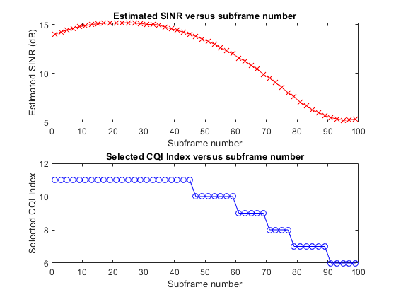
A figure with two subplots is produced. The first subplot shows the estimated SINR for each subframe; the second subplot shows the reported CQI for each subframe. This illustrates how the SINR and corresponding reported CQI vary over time due to the fading channel.
figure; subplot(2,1,1); plot(xaxis,SINRReport,'rx-'); xlabel('Subframe number'); ylabel('Estimated SINR (dB)'); title('Estimated SINR versus subframe number'); holdon; subplot(2,1,2); plot(xaxis,CQIReport,'bo-'); xlabel('Subframe number'); ylabel('Selected CQI Index'); title('Selected CQI Index versus subframe number');
Selected Bibliography
3GPP TS 36.101 "User Equipment (UE) radio transmission and reception"
You can also select a web site from the following list:
Americas
- América Latina(Español)
- Canada(English)
- United States(English)
Europe
- Belgium(English)
- Denmark(English)
- Deutschland(Deutsch)
- España(Español)
- Finland(English)
- France(Français)
- Ireland(English)
- Italia(Italiano)
- Luxembourg(English)
- Netherlands(English)
- Norway(English)
- Österreich(Deutsch)
- Portugal(English)
- Sweden(English)
- Switzerland
- United Kingdom(English)