Estimate Orientation and Height Using IMU, Magnetometer, and Altimeter
This example shows how to fuse data from a 3-axis accelerometer, 3-axis gyroscope, 3-axis magnetometer (together commonly referred to as a MARG sensor for Magnetic, Angular Rate, and Gravity), and 1-axis altimeter to estimate orientation and height.
Simulation Setup
This simulation processes sensor data at multiple rates. The IMU (accelerometer and gyroscope) typically runs at the highest rate. The magnetometer generally runs at a lower rate than the IMU, and the altimeter runs at the lowest rate. Changing the sample rates causes parts of the fusion algorithm to run more frequently and can affect performance.
% Set the sampling rate for IMU sensors, magnetometer, and altimeter.imuFs = 100;altFs = 10;magFs = 25;imuSamplesPerAlt = fix(imuFs/altFs); imuSamplesPerMag = fix(imuFs/magFs);% Set the number of samples to simulate.N = 1000;% Construct object for other helper functions.hfunc = Helper10AxisFusion;
Define Trajectory
The sensor body rotates about all three axes while oscillating in position vertically. The oscillations increase in magnitude as the simulation continues.
% Define the initial state of the sensor bodyinitPos = [0, 0, 0];% initial position (m)initVel = [0, 0, -1];% initial linear velocity (m/s)initOrient = ones(1,'quaternion');% Define the constant angular velocity for rotating the sensor body% (rad/s).angVel = [0.34 0.2 0.045];% Define the acceleration required for simple oscillating motion of the% sensor body.fc = 0.2; t = 0:1/imuFs:(N-1)/imuFs; a = 1; oscMotionAcc = sin(2*pi*fc*t); oscMotionAcc = hfunc.growAmplitude(oscMotionAcc);% Construct the trajectory objecttraj = kinematicTrajectory('SampleRate', imuFs,...'Velocity', initVel,...'Position', initPos,...'Orientation', initOrient);
Sensor Configuration
The accelerometer, gyroscope and magnetometer are simulated usingimuSensor. The altimeter is modeled using thealtimeterSensor. The values used in the sensor configurations correspond to real MEMS sensor values.
imu = imuSensor('accel-gyro-mag','SampleRate', imuFs);% Accelerometerimu.Accelerometer.MeasurementRange = 19.6133; imu.Accelerometer.Resolution = 0.0023928; imu.Accelerometer.ConstantBias = 0.19; imu.Accelerometer.NoiseDensity = 0.0012356;% Gyroscopeimu.Gyroscope.MeasurementRange = deg2rad(250); imu.Gyroscope.Resolution = deg2rad(0.0625); imu.Gyroscope.ConstantBias = deg2rad(3.125); imu.Gyroscope.AxesMisalignment = 1.5; imu.Gyroscope.NoiseDensity = deg2rad(0.025);% Magnetometerimu.Magnetometer.MeasurementRange = 1000; imu.Magnetometer.Resolution = 0.1; imu.Magnetometer.ConstantBias = 100; imu.Magnetometer.NoiseDensity = 0.3/sqrt(50);% altimeteraltimeter = altimeterSensor('UpdateRate', altFs,'NoiseDensity', 2*0.1549);
Fusion Filter
Construct anahrs10filterand configure.
fusionfilt = ahrs10filter; fusionfilt.IMUSampleRate = imuFs;
Set initial values for the fusion filter.
initstate = zeros(18,1); initstate(1:4) = compact(initOrient); initstate(5) = initPos(3); initstate(6) = initVel(3); initstate(7:9) = imu.Gyroscope.ConstantBias/imuFs; initstate(10:12) = imu.Accelerometer.ConstantBias/imuFs; initstate(13:15) = imu.MagneticField; initstate(16:18) = imu.Magnetometer.ConstantBias; fusionfilt.State = initstate;
Initialize the state covariance matrix of the fusion filter. The ground truth is used for initial states, so there should be little error in the estimates.
icv = diag([1e-8*[1 1 1 1 1 1 1], 1e-3*ones(1,11)]); fusionfilt.StateCovariance = icv;
Magnetometer and altimeter measurement noises are the observation noises associated with the sensors used by the internal Kalman filter in theahrs10filter. These values would normally come from a sensor datasheet.
magNoise = 2*(imu.Magnetometer.NoiseDensity(1).^2)*imuFs; altimeterNoise = 2*(altimeter.NoiseDensity).^2 * altFs;
Filter process noises are used to tune the filter to desired performance.
fusionfilt.AccelerometerNoise = [1e-1 1e-1 1e-4]; fusionfilt.AccelerometerBiasNoise = 1e-8; fusionfilt.GeomagneticVectorNoise = 1e-12; fusionfilt.MagnetometerBiasNoise = 1e-12; fusionfilt.GyroscopeNoise = 1e-12;
Additional Simulation Option : Viewer
By default, this simulation plots the estimation errors at the end of the simulation. To view both the estimated position and orientation along with the ground truth as the simulation runs, set theusePoseViewervariable totrue.
usePoseViewer = false;
Simulation Loop
q = initOrient; firstTime = true; actQ = zeros(N,1,'quaternion');expQ = zeros(N,1,'quaternion');actP = 0 (N, 1);expP= zeros(N,1);forii = 1: N% Generate a new set of samples from the trajectory generatoraccBody = rotateframe(q, [0 0 +oscMotionAcc(ii)]); omgBody = rotateframe(q, angVel); [pos, q, vel, acc] = traj(accBody, omgBody);% Feed the current position and orientation to the imuSensor object[accel, gyro, mag] = imu(acc, omgBody, q); fusionfilt.predict(accel, gyro);% Fuse magnetometer samples at the magnetometer sample rateif~mod(ii,imuSamplesPerMag) fusemag(fusionfilt, mag, magNoise);end% Sample and fuse the altimeter output at the altimeter sample rateif~mod(ii,imuSamplesPerAlt) altHeight = altimeter(pos);% Use the |fusealtimeter| method to update the fusion filter with% the altimeter output.fusealtimeter(fusionfilt,altHeight,altimeterNoise);end% Log the actual orientation and position[actP(ii), actQ(ii)] = pose(fusionfilt);% Log the expected orientation and positionexpQ(ii) = q; expP(ii) = pos(3);ifusePoseViewer hfunc.view(actP(ii), actQ(ii),expP(ii), expQ(ii));%#ok<*UNRCH>endend
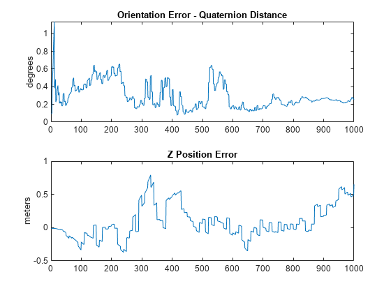
Plot Filter Performance
Plot the performance of the filter. The display shows the error in the orientation using quaternion distance and height error.
hfunc.plotErrs(actP, actQ, expP, expQ);
Conclusion
This example shows how to theahrs10filterto perform 10-axis sensor fusion for height and orientation.
You can also select a web site from the following list:
Americas
- América Latina(Español)
- 加拿大(English)
- United States(English)
Europe
- Netherlands(English)
- Norway(English)
- Österreich(Deutsch)
- Portugal(English)
- Sweden(English)
- Switzerland
- United Kingdom(English)