LTE Waveform Modeling Using Downlink Transport and Physical Channels
This example shows how to generate a time domain waveform containing a Physical Downlink Shared Channel (PDSCH), corresponding Physical Downlink Control Channel (PDCCH) transmission and the Physical Control Format Indicator Channel (PCFICH), for one subframe.
Introduction
This example demonstrates how to generate a complete Downlink Shared Channel (DL-SCH) transmission for 6 resource blocks, 4 antenna transmit diversity using the functions from the LTE Toolbox™. The following physical channels are modeled:
Physical Downlink Shared Channel (PDSCH)
Physical Downlink Control Channel (PDCCH)
Physical Downlink Control Format Indicator Channel (PCFICH)
This example generates a time domain (post OFDM modulation) for all 4 antenna ports. A single subframe (number 0) is considered in this example.
Note: The recommended way to generate RMC waveforms is usinglteRMCDLTool, this example shows how a waveform can be built by creating and combining individual physical channels, as happens in an LTE system.
Cell-wide Settings
eNodeB settings are configured with a structure.
enb。NDLRB = 6;% No of Downlink Resource Blocks(DL-RB)enb。CyclicPrefix ='Normal';% CP lengthenb。PHICHDuration ='Normal';% Normal PHICH durationenb。DuplexMode ='FDD';% FDD duplex modeenb。CFI = 3;% 4 PDCCH symbolsenb。Ng ='Sixth';% HICH groupsenb。CellRefP = 4;% 4-antenna portsenb。NCellID = 10;% Cell idenb。NSubframe = 0;% Subframe number 0
Subframe Resource Grid Generation
A resource grid can easily be created using the0LResourceGridfunction. This creates an empty resource grid for one subframe. The subframe is a 3 dimensional matrix. The number of rows represents the number of subcarriers available, this is equal to12*enb.NDLRBsince there are 12 subcarriers per resource block. The number of columns equals the number of OFDM symbols in a subframe, i.e. 7*2, since we have 7 OFDM symbols per slot for normal cyclic prefix and there are 2 slots in a subframe. The number of planes (3rd dimension) in subframe is 4 corresponding to the 4 antenna ports as specified inenb。CellRefP.
subframe = lteDLResourceGrid(enb);
DL-SCH and PDSCH Settings
The DL-SCH and PDSCH are configured using a structurepdsch. The settings here configure 4 antenna transmit diversity with QPSK modulation.
pdsch.NLayers = 4;% No of layerspdsch.TxScheme ='TxDiversity';% Transmission schemepdsch.Modulation ='QPSK';% Modulation schemepdsch.RNTI = 1;% 16-bit UE-specific maskpdsch.RV = 0;% Redundancy Version
PDSCH映射指数几代n
The indices to map the PDSCH complex symbols to the subframe resource grid are generated usingltePDSCHIndices. The parameters required by this function include some of the cell-wide settings inenb, channel transmission configurationpdschand the physical resource blocks (PRBs). The latter indicates the resource allocation for transmission of the PDSCH. In this example we have assumed all resource blocks are allocated to the PDSCH. This is specified using a column vector as shown below.
These indices are made '1based' for direct mapping on the resource grid as MATLAB® uses 1 based indexing. In this case we have assumed that both slots in the subframe share the same resource allocation. It is possible to have different allocations for each slot by specifying a two column matrix as allocation, where each column will refer to each slot in the subframe.
The resulting matrixpdschIndiceshas 4 columns, each column contains a set of indices in linear style pointing to the resource elements to be used for the PDSCH in each antenna port. Note that this function returns indices avoiding resource elements allocated to reference signals, the control region, broadcast channels and synchronization signals.
The generated indices are represented in 1-base format as used by MATLAB but can be made standard specific 0-based using the option'0based'instead of'1based'. If this option is not specified the default is 1-based index generation.
The coded block size for DL-SCH transmission can be calculated by theltePDSCHIndicesfunction. TheltePDSCHIndicesfunction returns an information structure as its second output, which contains the parameterGwhich specifies the number of coded and rate-matched DL-SCH data bits to satisfy the physical PDSCH capacity. This value will be used subsequently to parameterize the DL-SCH channel coding.
pdsch.PRBSet = (0:enb.NDLRB-1).';% Subframe resource allocation[pdschIndices,pdschInfo] =...ltePDSCHIndices(enb, pdsch, pdsch.PRBSet, {'1based'});
DL-SCH Channel Coding
We now generate the DL-SCH bits and apply channel coding. This includes CRC calculation, code block segmentation and CRC insertion, turbo coding, rate matching and code block concatenation. It can be performed using0LSCH.
The DL-SCH transport block size is chosen according to rules in TS36.101, Annex A.2.1.2 [1] "Determination of payload size" with target code rate and number of bits per subframe given by
codedTrBlkSize.
codedTrBlkSize = pdschInfo.G;% Available PDSCH bitstransportBlkSize = 152;% Transport block sizedlschTransportBlk = randi([0 1], transportBlkSize, 1);% Perform Channel CodingcodedTrBlock = lteDLSCH(enb, pdsch, codedTrBlkSize,...dlschTransportBlk);
PDSCH Complex Symbols Generation
以下操作应用于编码transport block to generate the Physical Downlink Shared Channel complex symbols: scrambling, modulation, layer mapping and precoding. This can be achieved usingltePDSCH. As well as some of the cell-wide settings specified inenbthis function also requires other parameters related to the modulation and channel transmission configuration,pdsch. The resulting matrixpdschSymbolshas 4 columns. Each column contains the complex symbols to map to each antenna port.
pdschSymbols = ltePDSCH(enb, pdsch, codedTrBlock);
PDSCH Mapping
The complex PDSCH symbols are then easily mapped to each of the resource grids for each antenna port using a simple assignment operation. The locations of the PDSCH symbols in the resource grids are given bypdschIndices.
% PDSCH地图符号资源网格subframe(pdschIndices) = pdschSymbols;
DCI Message Configuration
Downlink Control Information (DCI), conveys information about the DL-SCH resource allocation, transport format, and information related to the DL-SCH hybrid ARQ.0CIcan be used to generate a DCI message to be mapped to the Physical Downlink Control Channel (PDCCH). These parameters include the number of downlink Resource Blocks (RBs), the DCI format and the Resource Indication Value (RIV). The RIV of 26 correspond to full bandwidth assignment. The0CIfunction returns a structure and a vector containing the DCI message bits. Both contain the same information. The structure is more readable, while the serialized DCI message is a more suitable format to send to the channel coding stages.
dci.DCIFormat ='Format1A';% DCI message formatdci.Allocation.RIV = 26;% Resource indication value[dciMessage, dciMessageBits] = lteDCI(enb, dci);% DCI message
DCI Channel Coding
The DCI message bits are channel coded. This includes the following operations: CRC insertion, tail-biting convolutional coding and rate matching. The fieldPDCCHFormatindicates that one Control Channel Element (CCE) is used for the transmission of PDCCH, where a CCE is composed of 36 useful resource elements.
pdcch.NDLRB = enb.NDLRB;% Number of DL-RB in total BWpdcch.RNTI = pdsch.RNTI;% 16-bit value numberpdcch.PDCCHFormat = 0;% 1-CCE of aggregation level 1% Performing DCI message bits coding to form coded DCI bitscodedDciBits = lteDCIEncode(pdcch, dciMessageBits);
PDCCH Bits Generation
The capacity of the control region depends on the bandwidth, the Control Format Indicator (CFI), the number of antenna ports and the PHICH groups. The total number of resources available for PDCCH can be calculated usingltePDCCHInfo. This returns a structurepdcchInfowhere the different fields express the resources available to the PDCCH in different units: bits, CCEs, Resource Elements (REs) and Resource Elements Groups (REGs). The total number of bits available in the PDCCH region can be found in the fieldpdcchInfo.MTot. This allows us to build a vector with the appropriate number of elements. Not all the available bits in the PDCCH region are necessarily used. Therefore the convention adopted is to set unused bits to -1, while bit locations with values 0 or 1 are used.
Note that we have initialized all elements inpdcchBitsto -1, indicating that initially all the bits are unused. The elements ofcodedDciBitsare mapped to the appropriate locations inpdcchBits.
Only a subset of all the bits inpdcchBitsmay be used, these are called the candidate bits. Indices to these can be calculated usingltePDCCHSpace. This returns a two column matrix. Each row indicates the available candidate locations for the provided cell-wide settingsenband PDCCH configuration structurepdcch. The first and second columns contain the indices of the first and last locations respectively of each group of candidates. In this case these indices are 1-based and refer to bits, hence they can be used to access locations inpdcchBits. The vectorpdcchBitshas 664 elements. The 72 bits ofcodedDciBitsare mapped to the chosen candidate inpdcchBits. Therefore out of 664 elements, 72 will take 0 and 1 values, while the rest remain set to -1.ltePDCCHwill interpret these locations as unused and will only consider those with 1s and 0s.
pdcchInfo = ltePDCCHInfo(enb);% Get the total resources for PDCCHpdcchBits = -1*ones(pdcchInfo.MTot, 1);% Initialized with -1% Performing search space for UE-specific control channel candidatescandidates = ltePDCCHSpace(enb, pdcch, {'bits','1based'});% Mapping PDCCH payload on available UE-specific candidate. In this example% the first available candidate is used to map the coded DCI bits.pdcchBits( candidates(1, 1) : candidates(1, 2) ) = codedDciBits;
PDCCH Complex Symbol Generation
From the set of bits used inpdcchBits(values not set to -1) PDCCH complex symbols are generated. The following operations are required: scrambling, QPSK modulation, layer mapping and precoding.
TheltePDCCHfunction takes a set of PDCCH bits and generates complex-valued PDCCH symbols performing the operations mentioned above. In this case pdcchSymbols is a 4 column matrix, each corresponding to each antenna port.
pdcchSymbols = ltePDCCH(enb, pdcchBits);
PDCCH Mapping Indices Generation and Resource Grid Mapping
PDCCH indices are generated for symbol mapping on resource grid.pdcchIndicesis a matrix with 4 columns, one column per antenna port. The rows contain the indices in linear form for mapping the PDCCH symbols to the subframe resource grid.
pdcchIndices = ltePDCCHIndices(enb, {'1based'});% The complex PDCCH symbols are easily mapped to each of the resource grids% for each antenna portsubframe(pdcchIndices) = pdcchSymbols;
CFI Channel Coding
The number of OFDM symbols in a subframe is linked to the Control Format Indicator (CFI) value. Cell-wide settings structureenb指定一个CFI值3,这意味着4海底钻井M symbols are used for the control region in the case of 6 downlink resource blocks. The CFI is channel coded usinglteCFI. The resulting set of coded bits is a 32 element vector.
cfiBits = lteCFI(enb);
PCFICH Complex Symbol Generation
The CFI coded bits are then scrambled, QPSK modulated, mapped to layers and precoded to form the PCFICH complex symbols. ThepcfichSymbolsis a matrix having 4 columns where each column contains the PCFICH complex symbols that map to each of the antenna ports.
pcfichSymbols = ltePCFICH(enb, cfiBits);
PCFICH Indices Generation and Resource Grid Mapping
The PCFICH complex symbols are mapped to the subframe resource grid using the appropriate mapping indices. These are generated usingltePCFICHIndicesand will be used to map the PCFICH symbol quadruplets to resource element groups in the first OFDM symbol in a subframe. All antenna ports are considered, and resource elements used by Reference Signals (RSs) are avoided. Note that the resulting matrix has 4 columns; each column contains the indices in linear form for each antenna port. These indices are 1-based, however they can also be generated using 0-based. The linear indexing style used makes the resource grid mapping process straight forward. The resulting matrix contains the complex symbols inpcfichSymbolsin the locations specified bypcfichIndices.
pcfichIndices = ltePCFICHIndices(enb);% Map PCFICH symbols to resource gridsubframe(pcfichIndices) = pcfichSymbols;
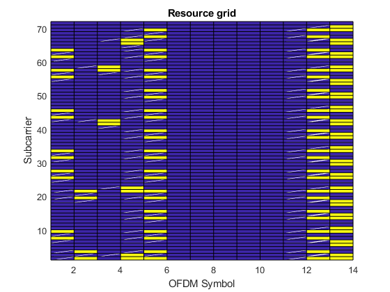
Plot Grid
Plot the resource grid for the first antenna. This includes (in yellow) the physical channels added in the example: PDSCH, PDCCH and PCFICH. Usesurf()to avoid aliasing. This plots the values (REs) of the grid and joins them with lines (for 12 subcarriers,surf()plots 12 points and 11 lines; thus, the last subcarrier is not visible). Repeat the last row of the resource grid so that the last subcarrier is visible.
surf(abs([subframe(:,:,1);subframe(end,:,1)])); view(2); h = rotate3d; setAllowAxesRotate(h,gca,false); axistight; xlabel('OFDM Symbol'); ylabel('Subcarrier'); title('Resource grid');
OFDM Modulation
Time domain mapping by performing OFDM modulation for downlink symbols. The resulting matrix has 4 columns; each column contains the samples for each antenna port.
[timeDomainMapped, timeDomainInfo] = lteOFDMModulate(enb, subframe);
Selected Bibliography
3GPP TS 36.101 "User Equipment (UE) radio transmission and reception"
You can also select a web site from the following list:
Americas
- América Latina(Español)
- Canada(English)
- United States(English)
Europe
- Belgium(English)
- Denmark(English)
- Deutschland(Deutsch)
- España(Español)
- Finland(English)
- France(Français)
- Ireland(English)
- Italia(Italiano)
- Luxembourg(English)
- Netherlands(English)
- Norway(English)
- Österreich(Deutsch)
- Portugal(English)
- Sweden(English)
- Switzerland
- United Kingdom(English)