设计MPC控制器for Position Servomechanism
此示例显示如何使用伺服机构使用的模型预测控制器MPC设计师。
System Model
A position servomechanism consists of a DC motor, gearbox, elastic shaft, and load.

代表该系统的微分方程是
在哪里,
V.是施加的电压。
T.是扭矩作用的扭矩。
是负载角速度。
电动机轴角速度。
其余项是恒定参数。
伺服机构模型的恒定参数
Symbol |
值(SI单位) |
Definition |
|---|---|---|
| K.T. | 1280.2 |
扭转刚性 |
| K.M. | 10. |
M.otor constant |
| jM. | 0.。5. |
电动机惯性 |
| jL. | 5.0.jM. |
L.oad inertia |
| ρ | 20. |
齿轮比 |
| βM. | 0.。1 |
M.otor viscous friction coefficient |
| βL. | 25. |
L.oad viscous friction coefficient |
| R. | 20. |
电枢抵抗 |
If you define the state variables as
然后您可以将伺服机构模拟为LTI状态空间系统。
这controller must set the angular position of the load,θL.,通过调整施加的电压,在所需值下,V.。
However, since the elastic shaft has a finite shear strength, the torque,T.那must stay within the range|T.|≤78.5nm.。另外,电压源实际将施加的电压限制为范围|V.|≤220V.。
构建工厂模型
指定模型常量。
Kt = 1280.2;%扭转刚度km = 10;% Motor constantjm = 0.5;%电机惯性jl = 50*Jm;% Load inertian = 20;% Gear ratioBm = 0.1;%转子粘性摩擦BL = 25;%负载粘性摩擦R.= 20;%电枢电阻
定义从模型方程导出的状态空间矩阵。
a = [0 1 0 0;-kt / jl -bl / jl kt /(n * jl)0;0 0 0 1;Kt /(JM * N)0 -KT /(JM * N ^ 2) - (BM + KM ^ 2 / R)/ JM];b = [0;0;0;KM /(R * JM)];c = [1 0 0 0;kt 0 -kt / n 0]; D = [0; 0];
创建状态空间模型。
植物= SS(A,B,C,D);
Open MPC Designer App
mpcDesigner
Import Plant and Define Signal Configuration
在MPC设计师那on theMPC设计师选项卡,选择M.PC Structure。
在定义MPC结构中通过导入对话框,选择植物植物model, and assign the plant I/O channels to the following signal types:
操纵变量 - 电压,V.
测量输出 - 负载角位置,θL.
Unmeasured output — Torque,T.

ClickDefine and Import。
MPC设计师imports the specified plant to theData Browser。这following are also added to theData Browser:
MPC1.- 默认的MPC控制器使用植物as its internal model.场景1.- 默认的仿真方案。此模拟的结果显示在输入响应and输出响应情节。
Define Input and Output Channel Attributes
On theMPC设计师标签,在结构部分,clickI / O属性。
在the Input and Output Channel Specifications dialog box, for each input and output channel:
Specify a meaningfulNameand单元。
保持Nominal Valueat its default value of
0.。Specify a比例因子for normalizing the signal. Select a value that approximates the predicted operating range of the signal:
Channel Name 最小值 最大限度imum Value 比例因子 电压–220 v 220 V. 440这ta-π弧度 π弧度 6.28扭矩–78.5 nm 78.5 Nm 15.7

ClickOK更新频道属性并关闭对话框。
M.odify Scenario To Simulate Angular Position Step Response
在theScenario部分,Edit Scenario下拉列表,选择场景1.修改默认模拟方案。
在the Simulation Scenario dialog box, specify a模拟持续时间of10.S.econds.
在the参考信号table, keep the default configuration for the first channel. These settings create aStepchange of1R.adian in the angular position setpoint at aT.imeof1S.econd.
对于第二个输出,信号下拉列表,选择Constant将扭矩设定值保持在其标称值。

ClickOK。
该应用程序使用新方案设置运行模拟并更新输入响应and输出响应情节。

指定控制器采样时间和视野
On theT.uning标签,在Horizon部分,指定一个Sample timeof0.。1S.econds.
对于指定的样本时间,T.S.,以及所需的响应时间T.R.= 2S.econds, select a prediction horizon,P.那S.uch that:
因此,指定一个预测地平线of20.。
Specify a控制地平线of5.。

当您更新示例时间和地平线值时输入响应and输出响应P.lots update automatically. Both the input voltage and torque values exceed the constraints defined in the system model specifications.
Specify Constraints
在the设计部分,S.electConstraints。
在the Constraints dialog box, in the在P.ut Constraints部分,指定M.inand最大限度操纵变量(MV)的电压值。
在theOutput Constraints部分,S.P.ecifyM.inand最大限度torque values for the unmeasured output (UO).

没有其他约束,即其他约束仍然存在于默认最大值和最小值,—Infandinf分别
ClickOK。

响应图更新以反映新的constR.aints. In the输入响应绘图,输入电压有不希望的大变化。
指定调整权重
在the设计部分,S.elect重量。
在权重对话框中,在输入权重表,增加操纵变量R.ate Weight。

调整重量for the manipulated variable (MV) is0.。该权重指示控制器可以允许输入电压在其约束范围内变化。增加R.ate Weight限制操纵变量变化的大小。
由于控制目标是负载的角度位置以跟踪其设定点,因此调整重量在测量的输出上是1。施加的扭矩没有设定值,因此控制器可以允许第二输出在其约束中变化。因此,这是重量在未衡量的输出(UO)上是0.那which enables the controller to ignore the torque setpoint.
ClickOK。

响应绘图更新以反映增加的率重量。这输入响应电压变化较小的更平滑。
Examine Output Response
在the输出响应情节,右键单击这ta绘图区域,选择Characteristics>Peak Response。

峰值输出响应发生在3秒的时间,最大超冲压为3%。由于参考信号步骤更改为1秒,因此控制器的峰值时间为2秒。
改善控制器响应时间
单击并拖动Closed-Loop PerformanceS.lider to the right to produce a moreAggressive回复。将滑块向右拖动越远,控制器响应越快。选择一个滑块位置,使峰值响应发生在2.7秒。

最终控制器峰值时间为1.7秒。减少响应时间进一步导致过于激进的输入电压变化。
生成和运行M.ATLAB脚本
在the分析部分,单击Export Controller箭![]() 。
。
UnderExport Controller那click生成脚本。
在the Generate MATLAB®脚本对话框,选中旁边的框场景1.。
Click生成脚本。
这app exports a copy of the plant model,植物_C,到MATLAB工作区,以及仿真输入和参考信号。
Additionally, the app generates the following code in the MATLAB Editor.
%%使用采样时间创建MPC控制器对象MPC1 = MPC(Plant_c,0.1);%% specify prediction horizonmpc1.predictionhorizon = 20;%%指定控制范围MPC1.。ControlHorizon = 5;%%指定输入和输出的标称值MPC1.。M.odel.Nominal.U = 0; mpc1.Model.Nominal.Y = [0;0];%%为输入和输出指定比例因子MPC1.mv(1).scalefactor = 440;mpc1.ov(1).scalefactor = 6.28;mpc1.ov(2).scalefactor = 157;%% specify constraints for MV and MV RateMPC1.mv(1).min = -220;mpc1.mv(1).max = 220;%% specify constraints for OVMPC1.。OV(2).Min = -78.5; mpc1.OV(2).Max = 78.5;%% specify overall adjustment factor applied to weightsBeta = 1.2712;%% specify weightsMPC1.。重量。M.V.=0.*beta; mpc1.Weights.MVRate = 0.4/beta; mpc1.Weights.OV = [1 0]*beta; mpc1.Weights.ECR = 100000;%% specify simulation options选项= mpcsimopt();options.reflookahead =.'off';options.MDLookAhead ='off';options.Constraints ='在';options.openloop =.'off';%%运行模拟SIM(MPC1,101,MPC1_REFSignal,MPC1_MDSignal,选项);
在the MATLAB Window, in theEditor选项卡,选择Save。
完成“保存”对话框,然后单击Save。
在theEditor选项卡,单击R.un。


脚本创建控制器,MPC1.,并运行模拟方案。输入和输出响应与应用程序的仿真结果匹配。
V.alidate Controller Performance In金宝app
If you have a Simulink®系统模型,您可以模拟控制器并验证其性能。金宝appSimulink功能不支持金宝appM.ATLAB Online™。
Open the model.
open_system('mpc_motor'的)

此模型使用MPC控制器控制伺服机构植物的阻滞。这Servomechanism Model块已被配置为使用植物model from the MATLAB workspace.
这角度参考源块创建具有频率的正弦参考信号0.。4R.ad/sec and an amplitude ofπ。
双击MPC控制器堵塞。
在“MPC控制器块参数”对话框中,指定一个MPC控制器from the MATLAB workspace. Use theMPC1.controller created using the generated script.

ClickOK。
At the MATLAB command line, specify a torque magnitude constraint variable.
tau = 78.5;
这model uses this value to plot the constraint limits on the torque output scope.
在Simuli金宝appnk模型窗口中,单击R.un模拟模型。

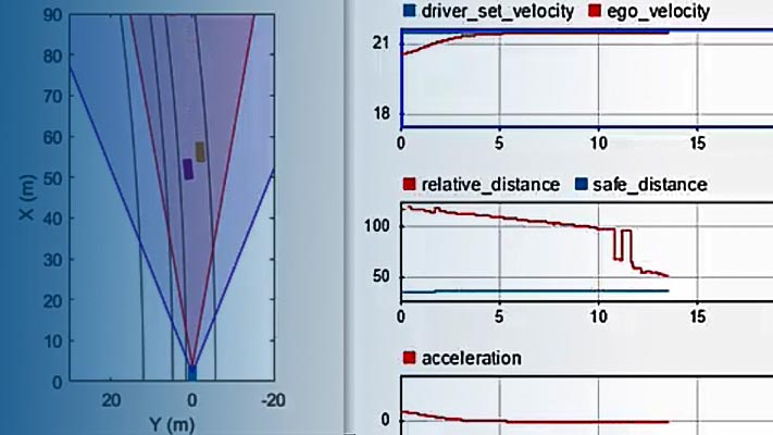
在theAngleS.cope, the output response, yellow, tracks the angular position setpoint, blue, closely.
也可以看看
R.elated Topics
您还可以从以下列表中选择一个网站:
美洲
- AméricaLatina(Español)
- 加拿大(English)
- 美国(English)
Europe
- Netherlands(English)
- Norway(English)
- Österreich.(德意志的)
- 葡萄牙(English)
- Sweden(English)
- 瑞士
- 单元ed Kingdom(English)