Design Matching Networks for Passive Multiport Network
此示例显示了如何针对5G mmwave系统的39 GHz的16端口被动网络设计匹配网络。匹配网络是针对每个端口独立设计的,每个生成的匹配网络均旨在在两个1端口终端之间运行。
设计多层无源网络
Compute the S-Parameters of a patch antenna array designed at 39 GHz. Load thesparams_patchArray.mat file. Thes_params_circ_array功能是从支持文件获得的金宝appdesignmultiport.mlx.
Fcenter = 39e9; load('sparams_patchArray.mat') Sparam_array = s_params_circ_array; show(patchArray) view([90 0])

Determine the index corresponding to the center frequency.
freq = sparam_array.frequencies;findex = find(freq == fcenter);
Create Matching Networks
Generate matching networks for each corresponding port independently, with a Loaded Q of 20 and configure the topology to 'Pi'. This Q-factor is aligned with half power bandwidth of the patch antenna array, which is approximately 2 GHz.
Define the number of ports in the network and specify the termination impedance.
numport = s_params_circ_array.NumPorts; ZT = 50; loadedQ = 20; topology ='pi';fori = 1 : numport% reflection coefficient/Siigam_array = s_params_circ_array.Parameters(i,i,fIndex);负载阻抗%Zout = gamma2z(gam_array);% Matching networks generationmatch_net(i)= matchingnetwork('SourceImpedance', ZT,。。。“载势”, Zout,“中心频率”, Fcenter,。。。'LoadedQ', loadedQ,'成分',拓扑);end
The source is connected to the component located on left of the matching network circuit and the load is connected to the component connected to the right of the matching network circuit. For the matching networks generated, the source is terminated with ZT (50 Ohm) and the load impedance is the impedance seen at the ith-port given by Zout.
查看并选择电路
Select a topology from the sixteen匹配网络objects. To get an overview of the available circuits, seecircuitDescriptionsfunction.
In this example, a Shunt C-Series L-Shunt C topology is used. If this topology is not available in your network, use the best available matching network circuit.
selectedCircuits = repmat(circuit,1,numport); cIndex = zeros(1,numport);
查看生成的电路列表。
fori = 1:numel(match_net)c = courtileDescriptions(match_net(i));%执行文本搜索以选择分流C系列L-shunt C拓扑的电路Index = strcmp(c.component1Type,"Shunt C")&。。。strcmp(c.component2Type,"Series L")&。。。strcmp(c.component3Type,"Shunt C");ifany(Index)% ShuntC-SeriesL-ShuntC topologycindex(i)=查找(索引,1,'第一的'); selectedCircuits(i) = match_net(i).Circuit(cIndex(i));else% Best available matchingnetworkselectedCircuits(i) = match_net(i).Circuit(1);endselectedCircuits(i).Name ="N"+i;end
To view the performance of a selected matching network circuit, useRFPLOT。例如,用并联C系列l-shunt c拓扑类型this命令绘制电路的第一个匹配网络的性能。
rfplot (match_net(1)、频率、cIndex (1));

将匹配的网络电路添加到16端口网络
Create Circuit Object
为16端口网络创建电路对象和N端口对象。
ckt = circuit('patchArray'); array_net = nport(Sparam_array);
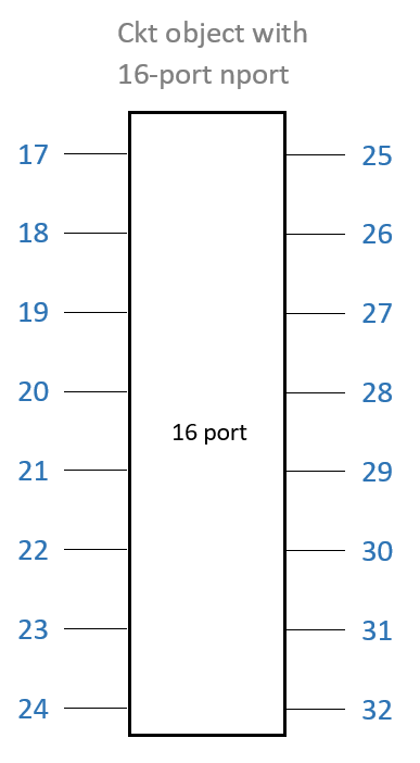
在此示例中,电路节点的数量显示为17,因为节点1至16将用于添加匹配网络。
cktnodes = (1+numport):(numport+numport);
Add the n-port object to circuit object.
add(ckt, cktnodes, array_net);
查看16端口网络的父节点。
disp(array_net)
nport: N-port element NetworkData: [1×1 sparameters] Name: 'Sparams' NumPorts: 16 Terminals: {1×32 cell} ParentNodes: [17 18 19 20 21 22 23 24 25 26 27 28 29 30 31 32 0 0 0 0 0 0 0 0 0 0 0 0 0 0 0 0] ParentPath: 'patchArray'
提供了带有16端口N端口的电路对象的插图。
Initialize the ports.
ports = cell(1,numport);
Add each matching network circuit to its corresponding port one at a time. Port numbers for corresponding matching network circuit are also generated.
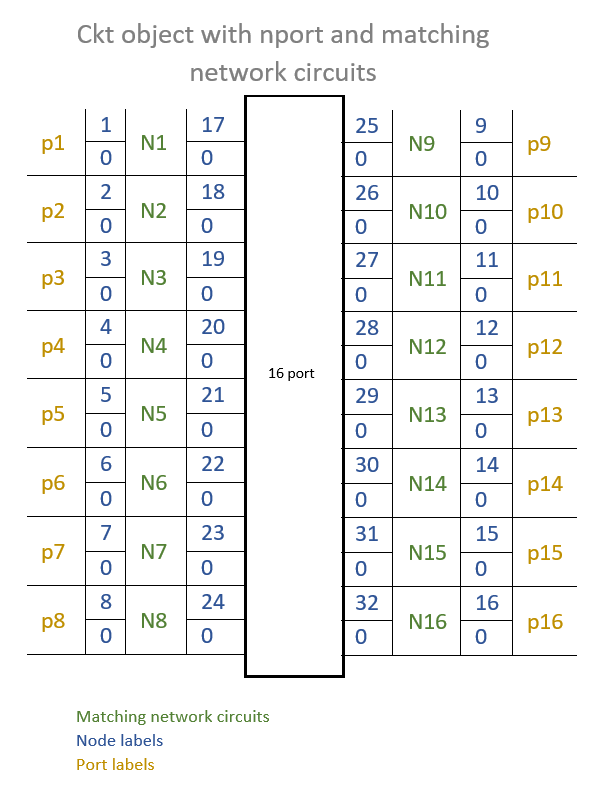
fori=1:length(selectedCircuits) add(ckt, [i, 0, i+numport, 0], selectedCircuits(i),。。。{'P1+','P1-','p2+','P2-'});端口{i} = [i,0];end% ports = arrayfun(@(x) [x 0],1:10,'UniformOutput',false);
Use thesetports功能以定义每个电路的端口。
setports(ckt,ports{:});
An illustration of the circuit object with n-port and matching network circuits are provided.
生成和Plot S-Parameters
生成和plot the S-Parameters of the passive 16-port matching network.
Sparam = Sparameters(CKT,FREQ);
Plot Frequency Responses
Plot the frequency response of the 16-port network before matching.
数字;RFPLOT(s_params_circ_array); legend离开

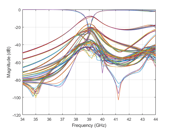
匹配后绘制16端口网络的频率响应。
数字;RFPLOT(SPARAM);传奇离开
相关话题
您还可以从以下列表中选择一个网站:
美洲
- AméricaLatina(Español)
- Canada(English)
- 美国(English)
欧洲
- Belgium(English)
- 丹麦(English)
- Deutschland(德意志)
- españa(Español)
- Finland(English)
- 法国(Français)
- 爱尔兰(English)
- 意大利(Italiano)
- Luxembourg(English)
- Netherlands(English)
- 挪威(English)
- Österreich(德意志)
- Portugal(English)
- Sweden(English)
- 瑞士
- 英国(English)