计算开环响应
控制系统的开环响应是植物和控制器的组合响应,不包括反馈回路的效果。例如,以下框图显示了一个单环控制系统。

我f the controller,C((s), and plant,p((s),是线性的,相应的开环传输函数为C((s)p((s)。

要删除反馈循环的效果,请在不手动破坏信号线的情况下插入循环打开分析点。从非线性模型手动删除反馈信号会更改模型操作点并产生不同的线性化模型。有关更多信息,请参阅软件如何处理循环开口。
如果不插入循环开口,则结果线性模型包括反馈循环的效果。

为了指定此示例的循环开口,您可以使用以下任何一个分析点。
| 分析点 | Description | 计算C((s)p((s) |
|---|---|---|
| 指定循环开口,然后进行输入扰动。 | 在控制器的输入处指定一个开环输入,并在工厂的输出处指定输出测量。
|
|
| Specifies an output measurement followed by a loop break. | Specify an open-loop output at the output of the plant and an input perturbation at the input of the controller.
|


For some systems, you cannot specify the loop opening at the same location as the linearization input or output point. For example, to open the outer loop in the following system, a loop opening point is added to the feedback path using a loop break analysis point![]() 。结果,只有蓝色块在线性化路径上。
。结果,只有蓝色块在线性化路径上。

placing the loop opening at the same location as the input or output signal would also remove the effect of the inner loop from the linearization result.
You can specify analysis points directly in your Simulink®模型,在Model Linearizer,或在命令行。有关更多信息,有关不同类型的分析点以及如何定义它们的信息,请参见指定模型的一部分以线性化。
计算开环响应UsingModel Linearizer
This example shows how to compute a linear model of the combined controller-plant system without the effects of the feedback signal. You can analyze the resulting linear model using, for example, a Bode plot.
Open Simulink model.
sys ='watertank'; open_system(sys)
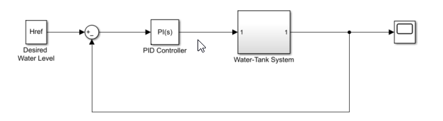
这Water-Tank Systemblock represents the plant in this control system and contains all of the system nonlinearities.
我n the Simulink model window, specify the portion of the model to linearize. For this example, specify the loop opening using open-loop output analysis point.
打开线性化标签。为此,在应用画廊,单击线性化管理器。
To specify an analysis point for a signal, click the signal in the model. Then, on the线性化tab, in the插入分析点画廊,选择分析点的类型。
Configure the input signal of thePID控制器块作为一个输入扰动。
配置输出信号Water-Tank System块作为一个开环输出。
Annotations appear in the model indicating which signals are designated as analysis points.

提示
如果您不想引入Simulink模型的更改,则可以指定分析点金宝appModel Linearizer。有关更多信息,请参阅指定模型的一部分以线性化in Model Linearizer。
打开Model Linearizerfor the model. In the Simulink model window, in the应用画廊,单击Model Linearizer。
默认情况下,analysis points you specified in the model are selected for linearization, as displayed in the分析I/OS下拉列表。

To linearize the model using the specified analysis points and generate a Bode plot of the linearized model, click![]() Bode。
Bode。
默认情况下,Model Linearizer在模型初始条件下线性化模型,如图所示操作点下拉列表。有关在不同操作点线性化模型的示例,请参见在修剪工作点线性化and在模拟快照上线性化。
提示
要生成响应类型以外的bode图,请单击绘图库中的“相应”按钮。
要查看模型的最小稳定边距,请右键单击Bode图,然后选择Characteristics>Minimum Stability Margins。

Bode图显示了相位边缘标记。要显示包含相位边距值的数据提示,请单击标记。

对于此系统,相位边的分频器为0.4 rad/s的90度。
在命令行计算开环响应
This example shows how to compute a linear model of the combined controller-plant system without the effects of the feedback signal. You can analyze the resulting linear model using, for example, a Bode plot.
Open Simulink model.
sys ='watertank'; open_system(sys)

指定模型的一部分,以通过使用该分析点创建一系列分析点来线性化linio命令:
开环输入point at the input of the PID Controller block. This signal originates at the output of the Sum1 block.
Output measurement at the output of the Water-Tank System block.
io(1)= linio('watertank/Sum1',1,“ openInput”);io(2)= linio('watertank/Water-Tank System',1,'输出');
开环输入分析点包括一个循环开口,该循环打破了信号流并消除反馈回路的效果。
使用默认模型操作点线性化模型线性化命令。
Linsys= linearize(sys,io);
Linsys是系统的线性化开环传输函数。现在,您可以通过例如绘制其频率响应并查看增益和相位边缘来分析响应。
利润(linsys)

对于此系统,增益边缘是无限的,并且相位边缘在0.4 rad/s的交叉频率下为90度。
也可以看看
Related Topics
You can also select a web site from the following list:
Americas
- América Latina((Español)
- Canada((English)
- United States((English)