Trajectory Planning for Robot Manipulators
注意:虽然这篇文章专门用于操纵器,但讨论的许多概念适用于其他类型的系统,如自动驾驶汽车和无人驾驶飞行器。
轨迹规划是一个整体问题的子集导航要么motion planning。The typical hierarchy of motion planning is as follows:
- 任务规划– Designing a set of high-level goals, such as “go pick up the object in front of you”.
- 路径规划– Generating a feasible path from a start point to a goal point. A path usually consists of a set of connected waypoints.
- 轨迹规划– Generating a time schedule for how to follow a path given constraints such as position, velocity, and acceleration.
- 轨迹后面- 一旦计划整个轨迹,需要有一个控制系统,可以以足够准确的方式执行轨迹。
最大的问题通常是“路径规划和轨迹规划之间有什么区别?”。如果你要拿走一件事:轨迹是如何遵循一段时间的轨迹,如下图片所示
在这篇文章中,我们将假设从我们的任务规划师的一组航点已经可用,我们希望为机器人生成一个轨迹,以随着时间的推移遵循这些航路点。我们将看看各种方式来构建和执行轨迹,并探索一些常见的设计权衡。
任务空间与联合空间
One of the first design choices you have is whether you want to generate ajoint-space要么任务空间弹道。
- Task space表示航线和插值位于操纵器上的特定位置的笛卡尔姿势(位置和方向) - 通常是末端执行器。
- Joint space表示航点和插值直接位于接头位置(角度或位移,这取决于关节的类型)
主要区别在于,任务空间轨迹往往比关节空间轨迹更加“自然”,因为即使关节不均匀,末端执行器也相对于环境平稳地移动。大缺点是,在任务空间轨迹之后涉及求解逆运动学(IK),而不是关节空间轨迹,这意味着很多more computation especially if your IK solver is based on optimization.
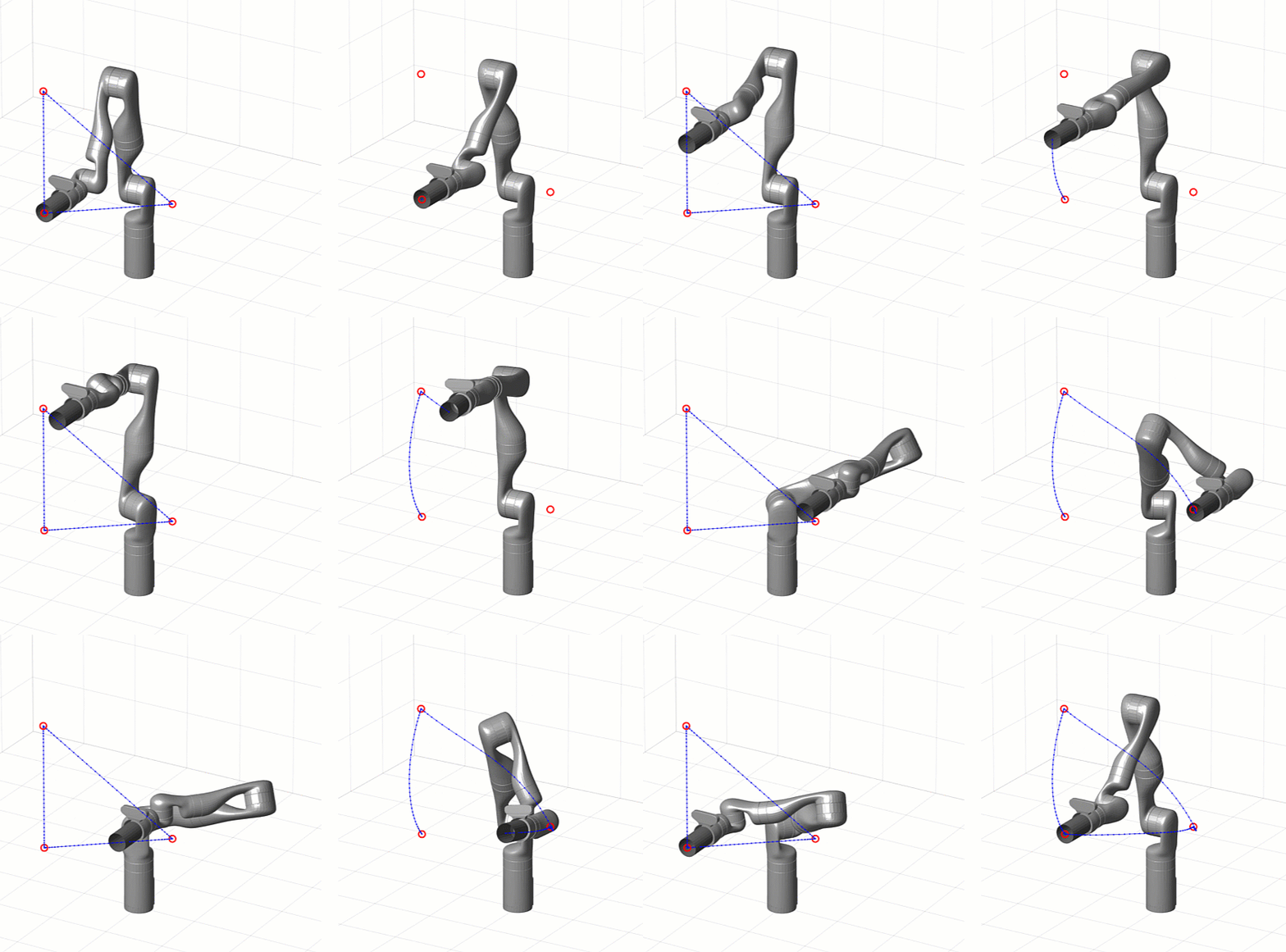 [左]任务空间轨迹[右]关节空间轨迹
您可以了解更多关于Sanipulator Kinematics的信息Robot Manipulation, Part 1: Kinematics blog post。下面的表还列出了优点和缺点of planning and executing trajectories in task space vs. joint space.
任务空间 |
联合空间 |
|
Pros |
|
|
Cons |
|
|
轨迹的类型
无论您是选择任务空间还是联合空间轨迹,都有各种方法可以在时间内创建插值姿势(或联合配置)的轨迹。我们现在将讨论一些最受欢迎的方法。
梯形速度
梯形速度轨迹是恒速加速度,零加速度和恒定减速的分段轨迹。这导致梯形速度曲线和“具有抛物线混合物”(LSPB)或S曲线位置轮廓的“线性段”。
该参数化使它们相对容易实现,调整和验证,以防止位置,速度和加速限制等要求。

With Robotics System Toolbox, you can use thetrapveltraj function在matlab或梯形速度Profile Trajectory blockin Simulink.
多项式
You can interpolate between two waypoints using polynomials of various orders. The most common orders used in practice are:
- 立方体(3.RD.订单) - 需要4个边界条件:两端的位置和速度
- Quintic(5.钍订单) - 需要6个边界条件:两端的位置,速度和加速度
类似地,高阶轨迹可用于匹配在航点处的高阶导数。
多项式trajectories are useful for continuously stitching together segments with zero or nonzero velocity and acceleration, because the acceleration profiles are smooth unlike with trapezoidal velocity trajectories. However, validating them is more difficult because instead of directly tuning maximum velocities and accelerations you are now setting boundary conditions that may be overshot between trajectory segments.

With Robotics System Toolbox, you can use thecubicpolytraj.和quinticpolytraj.在matlab中的功能,或多项式轨迹块in Simulink.
The animation below compares a trapezoidal velocity trajectory with zero velocity at the waypoints (left) and a quintic polynomial trajectory with nonzero velocity at the waypoints (right).

花键
构建插值轨迹的另一种方法是通过样条曲线。花键也是多项式的分段组合;但是与多项式轨迹不同,这些轨迹是多项式的时间(如此对于每个区段的多项式),样条是可用于产生复杂形状的空间中的多项式。通过以均匀速度遵循所产生的花键来进行时序方面。
有许多类型的样条曲线,但运动规划的一个常用类型是B样条(或基点)。通过定义花键不完全通过的中间控制点来参数化,而是保证留在这些点的凸壳内。作为设计师,您可以调整这些控制点以满足运动要求,而不担心这些点以外的轨迹。
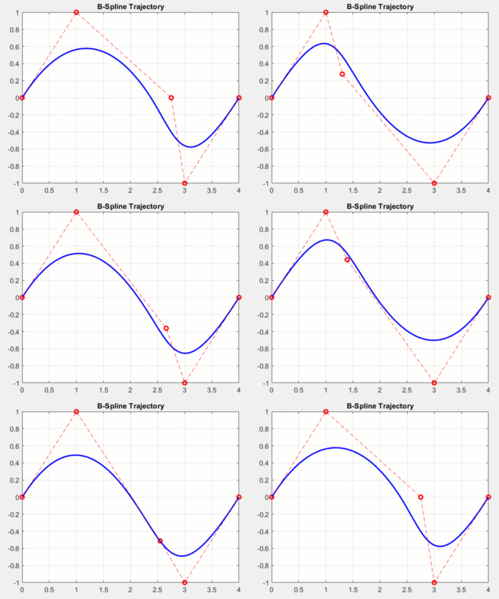 Effects of modifying control points for a 2D b-spline
在机器人系统工具箱中,您可以使用bsplinepolytraj function。
处理旋转
So far, we only showed you trajectories in position, but you probably also want to control the orientation of the end effector. Unlike positions, interpolating orientation can be a bit more challenging since angles are continuously wrapping. With some orientation representations like Euler angles there are multiple representations for the same configuration.
围绕这一点的一种方式是使用四元数来插入方向,这是一种毫不含糊地代表方向的方式。调用一种这种技术Spherical Linear Interpolation (Slerp),这在两个取向之间的最短路径,围绕固定轴的恒定角速度之间的两个取向。
With Robotics System Toolbox, you can use therottraj和Transfortraj.在matlab中的功能,或旋转轨迹和变换轨迹Simulink中的金宝app块分别。
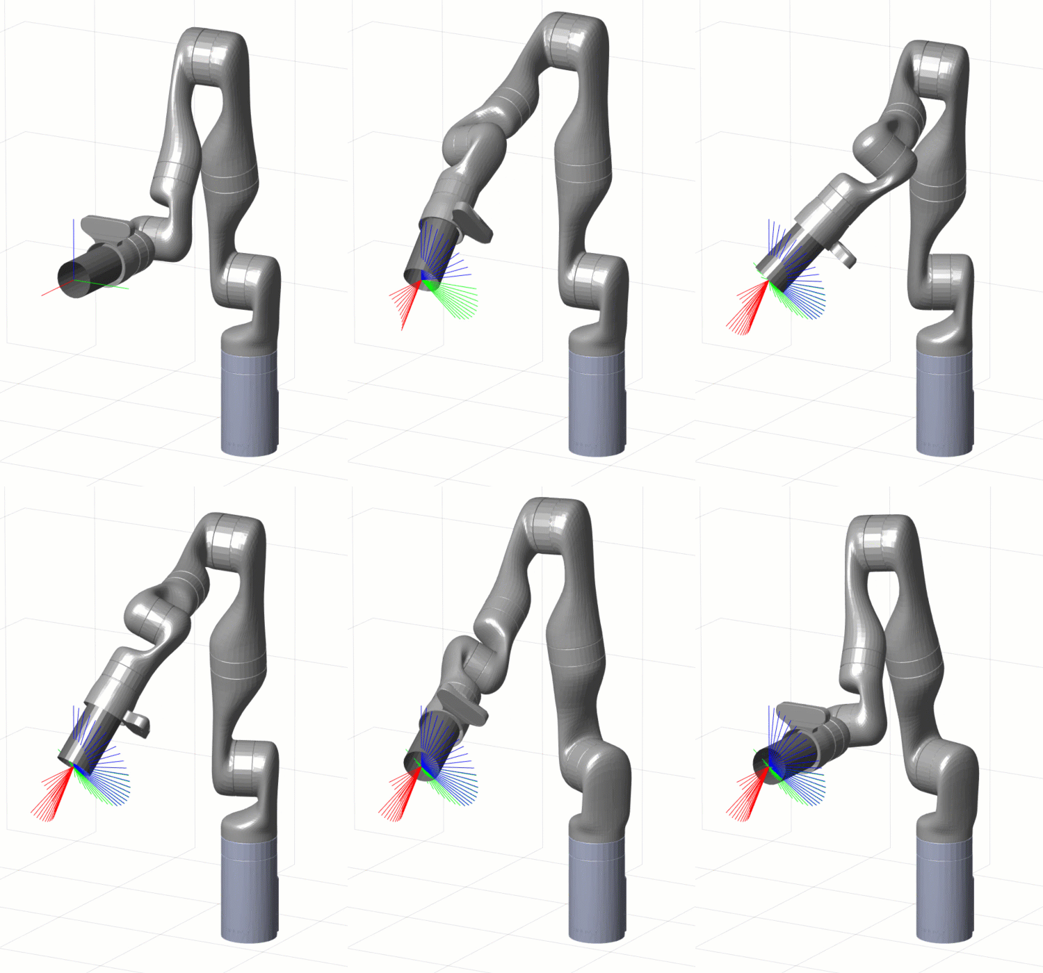 使用SLERP方法旋转轨迹在末端执行器上的轨迹
虽然SLERP在恒定速度下假定线性插值,但您可以包含所谓的内容time scaling改变轨迹的行为。您可以在统一的时间间距上对轨迹进行采样,而是可以将前一节中讨论的一些轨迹应用于“经线”时间向量。
例如,梯形速度时间缩放将导致轨迹开始和结束具有零速度的每个段,并在段的中间达到其最大速度。使用以下MATLAB命令,您可以创建和可视化具有梯形速度时间缩放的变换轨迹。
t0 = trvec2tform([0 0 0]);tf = trvec2tform([11/2 3])* Eul2tform([PI / 2 0 PI / 4],'ZYX');ttimes = linspace(0,1,51);tinterval = [0 5];[S,SD,SDD] = trapveltraj([0 1],numel(ttimes));[t,dt,ddt] = transformtraj(t0,tf,tinterval,ttimes,'timescaling',[s; sd; sdd]);plottransforms(tform2trvec(t),tform2quat(t));
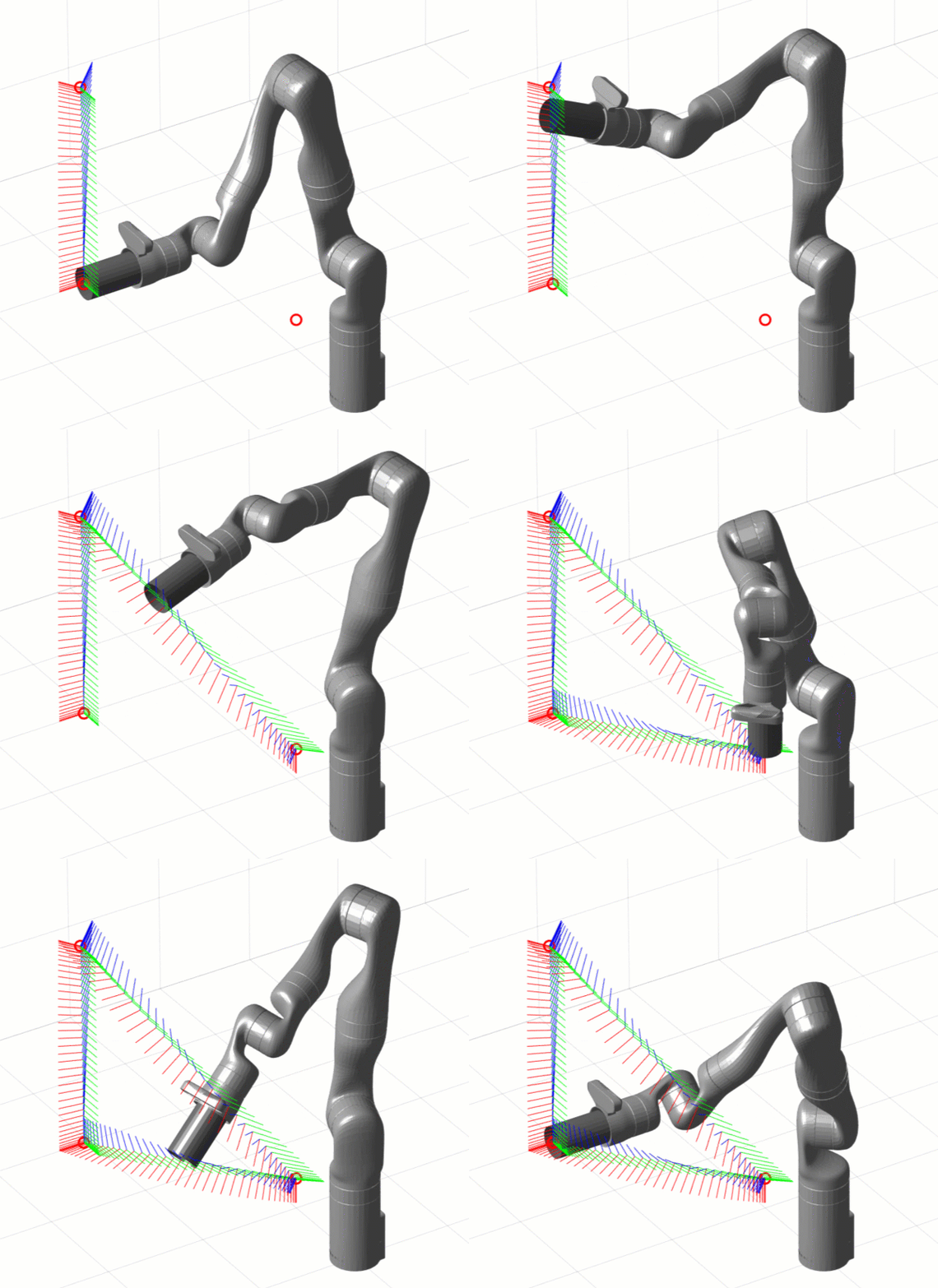 用梯形速度时间缩放变换轨迹
下一步是什么?
我们涵盖了几种方法可以为机器人操纵器产生运动轨迹。由于轨迹是参数,因此在任务空间或联合空间中,它们为我们提供了定位,速度和加速度的分析表达式。
具有可用的位置的参考衍生物有助于验证防止安全限制的轨迹,但对于机械手的低级控制也很好。例如,速度轨迹可以用作PID控制器的衍生分支的直接输入;或者您可以使用位置,速度和加速来计算前瞻性动态对于基于模型的控制器。如果您想了解更多关于机器人操纵器的低级控制,请退房our Robot Manipulation, Part 2: Dynamics and Control blog邮政。
As we did in this post, we started by designing trajectories on simple kinematic models. The next step is to try this using dynamic simulations – ranging anywhere fromsimple closed-loop motion modelsto a全3刚体仿真。
当然,最终目标是在您最喜欢的操纵器硬件上尝试此操作。
如果您想要更深入的轨迹规划知识,我发现了钍is presentation成为一个很好的资源。要了解更多有关Matlab和Simulink的轨迹规划,请观看我们的金宝app视频下面和从文件交换下载文件。
For anything else, leave us a comment below or email us atroboticsarena@mathworks.com.。


 Cleve’s Corner: Cleve Moler on Mathematics and Computing
 Loren在Matlab的艺术上
 史蒂夫在图像处理与matlab
 在simuli金宝appnk上的家伙
 Deep Learning
 Developer Zone
 Stuart’s MATLAB Videos
 Behind the Headlines
 本周的文件交换选择
 Hans on IoT
 Student Lounge
 初创公司,加速器和企业家
 MATLAB Community
 MATLAB ユーザーコミュニティー




コメント
コメントを残すには,ここをクリックしてMATHWORKSアカウントアカウントサインインするか新闻MATHWORKSアカウントを作品成します。