In the previous video, we talked about this architecture which implements a PWM-controlled buck converter to control a BLDC motor at varying speeds. In this video, we’ll show you an alternative implementation of PWM control, which we also discussed in detail in our third motor control Tech Talk video.
使第二个体系结构与第一个架构不同的原因是,它不使用Buck转换器降低直流源电压,而是直接调节三相电压。现在,我们将从该模型开始,该模型已经包含子系统,例如控制器,三相逆变器,BLDC和传感器。随时查看我们以前的视频,以了解如何使用Simscape Electrical库中的块来构建这些子系统。
在第一个体系结构中,我们在Buck Converter子系统下实现了PWM控件。在我们将要构建的新架构中,我们将在换向逻辑下实现PWM控件,在其中计算要发送到三相逆变器的开关模式。因此,让我们进入这个子系统。
Here, we see what we eventually want to achieve with this implementation. We want to modulate the three-phase voltages by taking the DC source voltage, which is 500 volts in this case, and using it to switch the voltages of the commutating phases between these two values— plus or minus half the DC source voltage. This way the effective voltage seen by the motor gets averaged.
我们已经拥有的当前逻辑代表了我们在第三次视频中构建的逻辑,但没有任何阶段切换。如果我们使用了这种逻辑,则通勤阶段将在整个相应扇区中用恒定电压通电。为了用PWM控件正确切换相位,如下所示,现在我们将修改此逻辑。
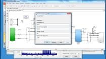
Note that during each PWM period, the commutating phases are switched between + and −250 volts in a complementary fashion. For example, during this period where we commutate phases A and B, while we drive phase A with positive voltage, phase B is driven with negative voltage and vice versa. To implement this, we first duplicate all of these blocks with the switching patterns and then reverse the bits of the commutating phases. For example, to reverse this switching pattern, we simply flip the 1s and 0s in the commutating phases A and C. After completing this for the remaining switching patterns, now we add a PWM generator and a switch and connect these together like this.
PWM发电机的输入是由控制器计算的占空比。因此,我们上升并输入该信号到换向逻辑,该逻辑会在子系统中自动创建输入端口。然后,我们设置PWM频率和样品时间,该时间已在MATLAB工作区中预定义。接下来,我们将开关阈值更新为正值。这样,在PWM信号的打开时间期间,我们将根据当前扇区以及PWM循环的其余部分传递此部分的开关模式,我们将通过互补模式。
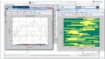
Now, this logic takes care of the phase switching properly. To see if it works correctly, let’s simulate this model and take a look at the logged signals. We see that the speed tracking is pretty good. The measured speed is shown in orange which makes it a little hard to see the desired speed that’s in green. This plot shows the DC source voltage of 500 volts, and here we see how it’s switched between + and −250 volts for the commutating phases. As a result of this switching, the motor will see an averaged voltage which will be similar to what’s shown with the dashed line.
请注意,在非交通阶段看到的后EMF电压有助于我们估计电动机看到的近似有效电压。例如,就在A阶段通勤之前,我们读取了-25伏的后EMF电压。因此,我们可以说电动机看到的有效相位A电压约为−25伏特。使用相同的逻辑,我们可以显示带有虚线在此处看到的阶段A,B和C的近似背面电压。
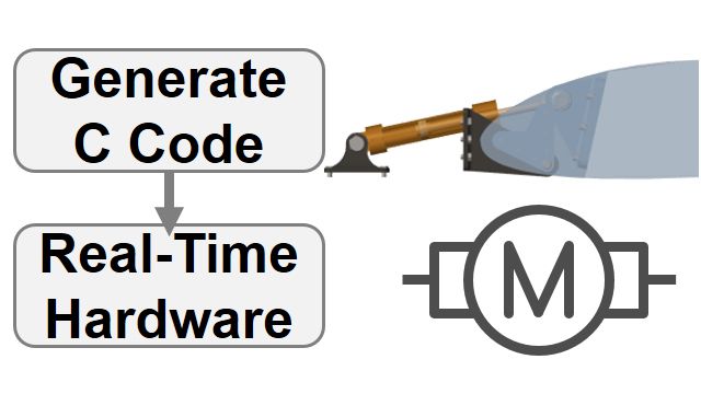
总之,在这个视频中,我们构建了一个模型来implement PWM control to directly modulate the three-phase voltages to a BLDC motor for controlling its speed at varying values. For more information on BLDC motor control, check out the links below this video.