Switched Beam Array With Butler Matrix
This example shows a switched beam array of 4 resonant dipoles. The beam switching is accomplished by using a 4 X 4 Butler matrix. The effect of the beam switching is shown by observing the outputs of 4 receiving antennas that are placed in the far-field of the array at the approximate azimuthal angles corresponding to the beam peaks. The effect of mutual coupling between the array elements on the transmit side is accounted for using S-parameters.
This example requires the following products:
RF Blockset
System Description
The system comprises of the following subsystems
信号源和端口开关
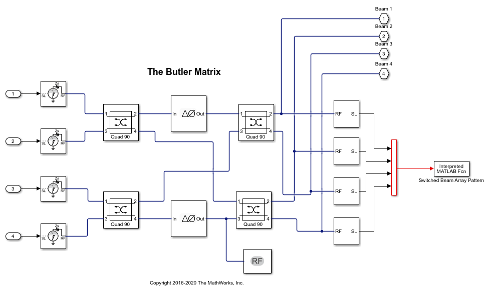
A 4 X 4 Butler matrix implemented using directional couplers and phase shifters
Array coupling model to capture the mutual coupling between the dipole linear array
Channel transfer function model between linear array and the receiving antennas in the far-field
model ='AtxSwitchedBeamArrayWithButlerMatrixModel';Open_System(模型);

Butler Matrix
The Butler matrix is a type of analog beamforming network that can be constructed from purely passive devices like directional couplers and phase shifters. The number of input and output ports in a Butler matrix are equal. The output ports are connected directly to each antenna element. Depending on the input port which is excited, the signals on the output ports are phase-shifted such that the beam switches in direction.
open_system([model'/Butler Matrix'],'力量');
Array Mutual Coupling Model, Channel and Receiving Antenna Output
The transmit side comprises of a 4 element linear array of resonant dipoles spaced half-wavelength apart. There are 4 receiving antennas, resonant dipoles, placed in the far-field of this array. These 4 dipoles are placed in the azimuthal plane at 15 degrees, 45 degrees, 315 degrees and 345 degrees. The locations correspond to the expected beam peaks from the switched beam array output. The response at each of these far-field receiving antenna elements is computed as a superposition of the contributions from each antenna element in the 4-element transmit array. The channel is assumed to be free-space. To capture the interactions on the transmit side and the transfer function from the transmit to receive antennas, we compute the overall scattering parameters for the transmit-receive system. This is done by using the conformalArray in Antenna Toolbox. The resulting 8-port S-parameter matrix is loaded into the S-parameters block in RF Blockset. The first 4 ports correspond to the transmit side antenna elements and the ports 5-8 belong to the individual receiving antennas in the far-field.
open_system([model'/tx-rx数组耦合模型'],'力量');

Run the Simulation
在模拟中,通过使用重复楼梯序列发生器切换通过信号驱动的输入端口。每个端口均以0.1 ms的速度激发。根据兴奋的端口,阵列主梁向方向开关。这可以在每个接收天线的输出信号水平中看到。在0.1 ms的时间块内,在4个接收的信号中,有1个占主导地位,其余三个表示波束形成的效果。
sim(model)


bdclose(model); clearmodel;
See Also
Select a Web Site
Choose a web site to get translated content where available and see local events and offers. Based on your location, we recommend that you select:.
Selectweb siteYou can also select a web site from the following list:
Americas
- AméricaLatina(Español)
- Canada(English)
- United States(English)
Europe
- Belgium(English)
- 丹麦(English)
- Deutschland(Deutsch)
- España(Español)
- Finland(English)
- 法国(Français)
- Ireland(English)
- Italia(Italiano)
- Luxembourg(English)
- Netherlands(English)
- 挪威(English)
- Österreich(Deutsch)
- Portugal(English)
- Sweden(English)
- Switzerland
- United Kingdom(English)