LTE Waveform Generation and Transmission Using Quick Control RF Signal Generator
此示例显示了如何使用LTE Toolbox™,仪器控制工具箱™和KeysightTechnologies®RF仪器生成和传输空中LTE波形。
Introduction
在此示例中,LTE工具箱用于生成标准基带IQ下行链路测试模型(E-TM)波形。使用仪器控制工具箱,将所生成的波形下载到Keysight Technologies N5172B信号发生器,用于过空气传输。使用Keysight Technologies N9010A信号分析仪捕获过空中信号。

For more information on LTE waveform generation and analysis, refer to使用测试和测量设备的LTE工具箱的波形生成和传输(LTE Toolbox)。
Requirements
要运行此示例,您需要:
Keysight Technologies N5172B signal generator
Keysight Technologies N9010A signal analyzer
Keysight VISA version 17.3
Keysight Technologies N5172B信号发生器的IVI-C驱动程序
National Instruments™IVI®合规包版16.0.1.2或更高版本
LTE工具箱
Instrument Control Toolbox
Generate a Baseband Waveform Using the LTE Toolbox
Generate test model waveform usingLTetestModeltool.(LTE Toolbox)那this returns an E-TM time-domain waveform,波形,在单个天线端口跨越多个子帧的资源元素的2-D数字数组,tmgrid.和标量结构,tmconfig,包含有关OFDM调制波形的信息。
config = lteTestModel('1.1'那'5MHz');%测试型号1.1,5MHz带宽config.totsubframes = 100;%生成100个子帧[波形,Tmgrid,TMConfig] = LTTESTMODELTOOL(CONFIG);
The frequency spectrum of the generated time domain waveform,波形那can be viewed using thedsp.spectrumanalyzer.(DSP System Toolbox)。As expected, the 5MHz signal bandwidth is clearly visible at baseband.
%计算LTE信号中的光谱内容SpectRumplottX = DSP.SpectRumanalyzer;spectumplottx.samplerve = tmconfig.samplingrate;spectrumplottx.spectrumtype ='Power density';spectrumplottx.powerunits =.'dbm';spectrumPlotTx.RBWSource ='财产';spectrumPlotTx.RBW = 15e3; spectrumPlotTx.FrequencySpan ='Span and center frequency';spectrumplottx.span = 7.68e6;spectrumplottx.Centerfrequency = 0;spectrumplottx.window ='长方形';spectrumplottx.spectralaverages = 10;spectrumplottx.ylimits = [-100 -60];spectrumplottx.ylabel ='psd';spectrumplottx.title ='Test Model E-TM1.1, 5 MHz Signal Spectrum';spectrumplottx.showlegend = false;Spectrumplottx(波形);

Generate an Over-the-Air Signal using Quick-Control RF Signal Generator
快速控制RF信号发生器用于下载并传输由LTE工具箱创建的测试模型波形,波形那using the Agilent Technologies N5172B signal generator. This creates an RF LTE signal with a center frequency of 1GHz. Note 1GHz was selected as an example frequency and is not intended to be a recognized LTE channel.
创建RF信号发生器对象
rf = rfsiggen();
发现您可以使用的所有可用仪器资源,使用resourcesmethod.
RF.。resources
ans ='asrl1 :: instrsssrl3 :: instrssasrl :: com1 asrl :: com3 tcpip0 :: 172.28.21.217 :: inst0 :: instr'
Discover all the available instrument drivers, using司机method.
RF.。司机
ANS ='驱动程序:AGRFSIGGEN_SCPI支持的型号金宝app:E4428C,E4428C驱动程序:RSRFSIGGEN_SCPI支持的型号:SMW200A,SMBV100A,SMU200A,SMJ100A,AMU200A,SMATE200A驱动程序:AGRFSIGGEN支持的型号:E4428C,E4438C,N5181A,N5171B,N5181B,N5171B,N5181B,N5172B,N5181B,N5172BN5182B,N5173B,N5183B,E8241A,E8244A,E8251A,E8254A,E8247C'
放Resourceand司机连接到对象之前的属性。Keysight Technologies N5172B信号发生器的IP地址是172.28.21.217因此,指定的资源将是'tcpip0 :: 172.28.21.217 :: inst0 :: instr'
rf.resource ='TCPIP0 :: 172.28.21.217 :: Inst0 :: instr';RF.。司机='Agrfsiggen';% Connect to the instrument连接(rf);
Download the waveform,波形,仪器
download(rf, transpose(waveform), tmconfig.SamplingRate);
称呼开始to start transmitting waveform using specifiedcenterFrequency那输出功率andloopcount.。Loop count represents the number of times the waveform should be repeated.
centerFrequency = 1e9; outputPower = 0; loopCount = Inf; start(rf, centerFrequency, outputPower, loopCount);
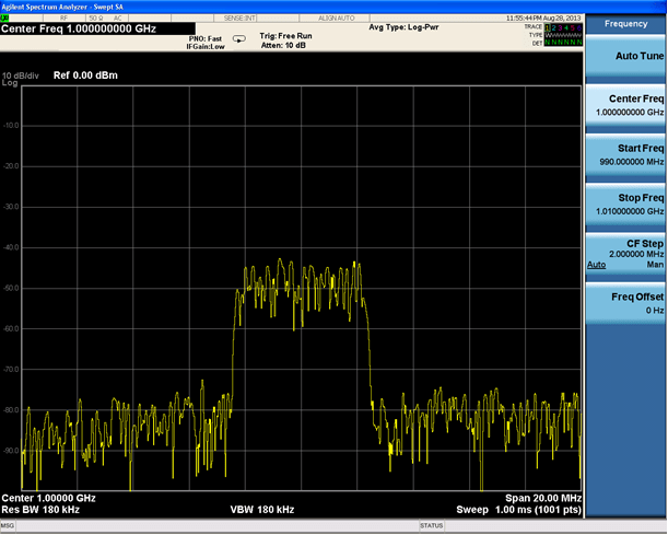
可以使用调谐到1GHz中心频率的频谱分析器来观察由信号发生器发送的RF信号的频谱。下面的屏幕截图,来自Agilent Technologies N9010A信号分析仪,清楚地显示了5MHz信号带宽。
清理
当您完成传输数据时,停止波形输出,断开连接RFSIGGEN.来自信号发生器的对象,并将其从工作区中删除。
停止(rf);断开(RF);清除RF.
You can also select a web site from the following list:
Americas
- América Latina(Español)
- 加拿大(英语)
- United States(英语)