LTE下行链路相邻通道泄漏功率比(ACLR)测量
此示例显示了如何使用LTE Toolbox™在下行链路参考测量通道(RMC)信号中测量相邻通道泄漏功率比率(ACLR)。
Introduction
此示例根据TS36.104,第6.6.2节[1]对于下行链路波形。ACLR用作泄漏到相邻通道的功率量的量度,并定义为以分配的通道频率与以相邻通道频率为中心的过滤平均功率相中的过滤平均功率。E-UTRA(LTE)载体和UTRA(W-CDMA)载体给出了最低ACLR一致性要求。
该示例的结构如下:
A downlink waveform is generated using a Reference Measurement Channel (RMC) configuration
Parameters for ACLR measurements are calculated including the required oversampling rate to ensure a signal capable of representing both the E-UTRA and UTRA 1st and 2nd adjacent carriers with at most 85% bandwidth occupancy
The waveform is oversampled as required
The E-UTRA ACLR is calculated using a square measurement filter
The UTRA ACLR is calculated using a Root Raise Cosine (RRC) filter
The ACLR measurements are displayed
Waveform Generation
A downlink RMC is used for measuring ACLR and created usingltermcdlandltermcdlTool。
%生成RMC R.6的下行链路配置结构cfg = lteRMCDL('r.6');% Generate the waveform which is a T-by-P matrix where T is the number of% time-domain samples and P is the number of receive antennas[waveform, ~, info] = lteRMCDLTool(cfg, [1; 0; 0; 1]);%将采样率和芯片速率写入配置结构% allow the calculation of ACLR parameterscfg.samplingrate = info.samplingrate;cfg.utrachiprate = 3.84;% UTRA chip rate in MCPS
计算ACLR参数
使用辅助功能计算ACLR测量所需的参数hACLRParameters.m。
Determine Required Oversampling.如果输入波形采样率(
cfg.SamplingRate) is not sufficient to span the entire bandwidth (aclr.BandwidthACLR)相邻通道(允许最大85%带宽占用率),波形必须使用UPSMPLAPLAPL,用于ACLR计算。aclr.OSRis the upsampling factor.Determine UTRA Parameters;the chip rates and bandwidths.
% Calculate ACLR measurement parameters[aclr, nRC, R_C, BWUTRA] = hACLRParameters(cfg);
执行波形过滤以改善ACLR
The waveform generated above has no filtering, so there are significant out of band spectral emissions owing to the implicit rectangular pulse shaping in the OFDM modulation (each OFDM subcarrier has a sinc shape in the frequency domain). In order to achieve a good ACLR performance, filtering must be applied to the waveform. A filter is designed with a transition band that starts at the edge of the occupied transmission bandwidth (aclr.BandwidthConfig) and stops at the edge of the overall channel bandwidth (aclr.Bandwidth). This filter involves no rate change, it just shapes the spectrum within the original bandwidth of the waveform. The filter is first designed, then applied to the waveform.
% Design filterfirfilter = dsp.lowpassfilter();firfilter.samplerate = info.samplingrate;firfilter.passbandfrequency = aclr.bandwidthconfig/2;firfilter.stopbandfrequency = aclr.bandwidth/2;%应用过滤器waveform = firFilter(waveform);
Calculate E-UTRA and UTRA ACLR
The ACLR for E-UTRA and UTRA is measured using two helper functions:
Haclrmeasurementeutra.m使用相邻通道上的方形窗口测量E-UTRA ACLR。采集测量信号的DFT和用于计算相邻通道功率的适当垃圾箱的能量。
Haclrmeasurementutra.mmeasures the UTRA ACLR using a RRC filter on adjacent channels with a roll-off factor of 0.22 and bandwidth equal to the chip rate.
%应用所需的过采样resampled = resample(waveform,aclr.OSR,1);%计算e-utra aclrACLR = Haclrmeasurementeutra(ACLR,重采样);% Calculate UTRA ACLRaclr = hACLRMeasurementUTRA(aclr, resampled, nRC, R_C, BWUTRA);
显示结果
The ACLR results are returned in structureaclr。aclr包含字段:
Bandwidth: The channel bandwidth associated withcfg.ndlrborcfg.NULRB, in Hertz. This is the overall bandwidth of the assigned channel.BandwidthConfig: The transmission bandwidth configuration associated withcfg.ndlrborcfg.NULRB, in Hertz. This is the bandwidth within the channel bandwidth that contains active subcarriers.BandwidthACLR:所需的带宽以表示E-UTRA和UTRA第一和第2个相邻载体所需的带宽;用于ACLR测量的内部采样率将以85%的带宽占用率支持此带宽。金宝appOSR:输入的整数过采样率waveformrequired to create a signal capable of representing both the E-UTRA and UTRA 1st and 2nd adjacent carriers i.e. to representaclr.BandwidthACLRwith at most 85% bandwidth occupancy.SamplingRate: The sampling rate of the internal measurement signal from which the ACLR is calculated. IfOSR=1, this signal is the input waveform; ifOSR>1, this signal is the input waveform upsampled byOSR。Therefore:aclr.SamplingRate = OSR*cfg.SamplingRate。EUTRAPowerdBm: The power, in decibels relative to 1mW in 1ohm, of the input within the E-UTRA channel of interest i.e. in a square filter of bandwidthaclr.BandwidthConfigcentered at 0Hz.EUTRAdB: A vector of E-UTRA ACLRs, in decibels relative toaclr.eutrapowerdbm, measured for adjacent channels [-2, -1, 1, 2].EUTRACenterFreq: A vector of E-UTRA center frequencies, in Hertz, for adjacent channels [-2, -1, 1, 2].UTRAPowerdBm: A vector of powers, in decibels relative to 1mW in 1ohm, of the input within the UTRA channel of interest; each element of the vector corresponds to each of the configured UTRA chip rates i.e.UTRAPowerdBm(i)gives the power of the input in an RRC filter designed forr = cfg.utrachiprate(i)Mchips/s,alpha = 0.22, centered at 0 Hz.Utradb:UTRA ACLR的矩阵,分贝相对于aclr.eutrapowerdbm。The columns give the values for adjacent channels [-2, -1, 1, 2] and the rows give the values for each of the configured UTRA chip rates. Note that as required by the standard, these ACLRs are relative toaclr.eutrapowerdbm, notaclr.UTRAPowerdBm。UTRACenterFreq: A matrix of UTRA center frequencies, in Hertz. The columns give the values for adjacent channels [-2, -1, 1, 2] and the rows give the values for each of the configured UTRA chip rates.
hACLRResults.m显示ACLR并绘制相邻的通道功率。根据TS 36.104表6.6.2.1-1 [1],配对频谱中基站的最小ACLR为45 dB。由于ACLR结果高于45 dB,因此它们属于要求。
minACLR = 45; hACLRResults(aclr,minACLR);
Bandwidth: 5000000 BandwidthConfig: 4500000 BandwidthACLR: 25000000 OSR: 4 SamplingRate: 30720000 EUTRACenterFreq: [-10000000 -5000000 5000000 10000000] EUTRAPowerdBm: -0.5918 EUTRAdB: [79.2357 72.1187 72.2046 79.2157] UTRAPowerdBm: -1.3397 UTRAdB: [80.3117 72.5323 72.5011 80.3540] UTRACenterFreq: [-10000000 -5000000 5000000 10000000]


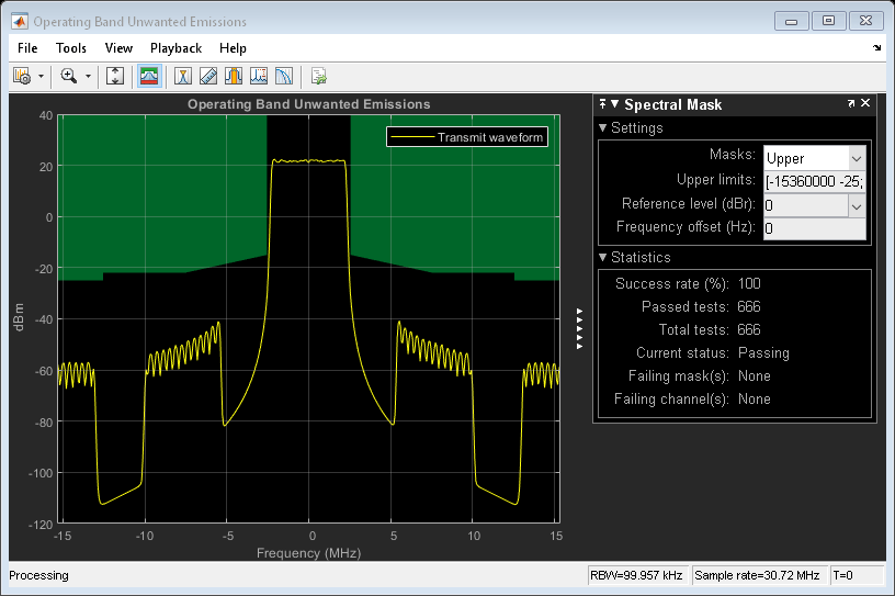
Operating Band Unwanted Emissions (Spectral Mask)
The waveform spectrum is displayed in conjunction with the transmit spectral mask defined in TS 36.104. This example assumes that the waveform corresponds to a Medium Range BS as described in TS 36.104 Table 6.2-1 and the power is set to 38.0dBm (~21.5dBm/100kHz). The corresponding spectral mask is provided in TS 36.104 Table 6.6.3.2C-5 "Medium Range BS operating band unwanted emission limits for 5, 10, 15 and 20MHz channel bandwidth, 31 < P_max,c <= 38dBm".
% Adjust waveform power to maximum rated output powerP_max = 38.0;% TS 36.104 Table 6.2-1bsWaveform = resampled * 10^((P_max-aclr.EUTRAPowerdBm)/20);%创建频谱分析仪,将其配置为波形采样率%和分辨率100kHz的带宽,配置并显示光谱% mask in TS 36.104 Table 6.6.3.2C-5, and perform spectrum analysis of the% waveformrbw = 100e3;%分辨率带宽vbw = 30e3;%视频带宽spectrumAnalyzer = dsp.SpectrumAnalyzer; spectrumAnalyzer.Name ='Operating Band Unwanted Emissions';spectrumAnalyzer.Title = spectrumAnalyzer.Name; spectrumAnalyzer.SampleRate = info.SamplingRate * aclr.OSR; spectrumAnalyzer.RBWSource ='Property';spectrumAnalyzer.RBW = rbw; spectrumAnalyzer.AveragingMethod ='Exponential';spectrumanalyzer.forgettingfactor = hvbw2ff(vbw,spectrumanalyzer.samplerate);spectrumanalyzer.showlegend = true;spectrumanalyzer.channelnames = {'Transmit waveform'};spectrumanalyzer.ylimits = [-120 40];%“测量过滤器中心频率的频率偏移”表中f_offset = [0.05; 5.05; 10.05; 10.05] * 1e6;% "Minimum requirement" in table (dBm/100kHz)mask_power = [(P_MAX-53);(P_MAX-60)*[1;1];min(p_max-60,-25)*[1;1];];%在频带边缘添加垂直面膜段;没有特定的内部力量% mask is required to be met for this testf_offset = [repmat(f_offset(1),2,1);f_offset];mask_power = [nan;Spectrumanalyzer.ylimits(2);mask_power];% Extend mask to analysis bandwidth edge, assumed to be closer to the edge利益载体的频率比F_OffSet_Max(偏移到% frequency 10MHz outside the downlink operating band)mask_freq = [f_offset + aclr.Bandwidth/2; spectrumAnalyzer.SampleRate/2];%添加一个镜像版本的面具cover negative frequencies, and%启用面具mask_power = [flipud(mask_power);mask_power];mask_freq = [-flipud(mask_freq);(mask_freq)];spectrumanalyzer.spectralmask.enabledmasks ='Upper';spectrumanalyzer.spectralmask.uppermask = [mask_freq,mask_power];% Perform spectrum analysisspectrumAnalyzer(bsWaveform);
Perform Downsampling and Measure EVM
Finally the waveform is downsampled and resynchronized and an EVM measurement is performed. For more information on making EVM measurements, seePDSCH Error Vector Magnitude (EVM) Measurement。根据TS 36.104表6.5.2-1 [1], the maximum EVM when the constellation is 64QAM is 8%. As the overall EVM, around 0.78%, is lower than 8%, this measurement falls within the requirements.
downsampled = resample(resampled,1,aclr.OSR); offset = lteDLFrameOffset(cfg,downsampled,'TestEVM'); cec.PilotAverage ='TestEVM';evmsettings.EnablePlotting ='Off';evm = hPDSCHEVM(cfg,cec,downsampled(1+offset:end,:),evmsettings);
低边缘EVM,副车架0:0.741%高边缘EVM,副车架0:0.707%低边缘EVM,副帧1:0.885%高边缘EVM,副帧1:0.789%低边缘EVM,子帧2:0.785%高边缘EVM,副率EVM,子段子段2:0.699%低边缘EVM,副车架3:0.698%高边缘EVM,副车架3:0.667%低边缘EVM,副车架4:0.817%高边缘EVM,副帧4:0.640%低边缘EVM,副率6:0.840%高帧高高。Edge EVM,副车架6:0.747%低边缘EVM,副车架7:0.732%高边缘EVM,副车架7:0.696%低边缘EVM,副车架8:0.742%高边evm,子帧8:0.745%平均总体EVM:0.7833%:0.7833%
Further Exploration
You can modify parts of this example to calculate ACLR (as per TS36.101, Section 6.6.2.3 [2]) for the uplink by usingltermculin the place ofltermcdlto generate the waveform.
附录
This example uses the following helper functions:
Selected Bibliography
3GPP TS 36.104 "Base Station (BS) radio transmission and reception"
3GPP TS 36.101 "User Equipment (UE) radio transmission and reception"
You can also select a web site from the following list:
Americas
- América Latina(Español)
- Canada(English)
- United States(English)
Europe
- Netherlands(English)
- Norway(English)
- Österreich(Deutsch)
- Portugal(English)
- 瑞典(English)
- Switzerland
- United Kingdom(English)