Oversampling Interpolating DAC
This example shows how to model a 12-bit Oversampling Interpolating DAC.
Oversampling Interpolating DACs use interpolation to achieve a higher resolution output than provided on their input. This allows less complicated output filtering for a DSP system operating close to its Nyquist rate.
Model
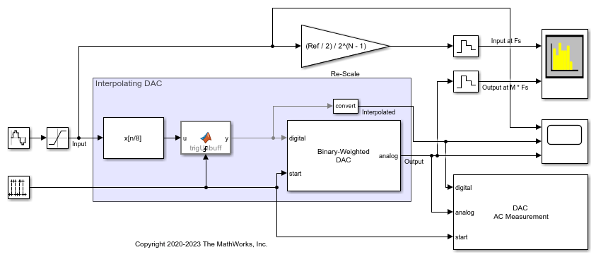
The oversampling interpolating DAC has three basic functional blocks. The first block is an FIR Interpolation filter block from the DSP System Toolbox™ to increase the sample rate from the input sample rate ofFsto the DAC's sample rate ofM * Fs. The second block is a MATLAB Function block that handles unbuffering the output of the FIR Interpolation block. The MATLAB Function block has a clock-triggered nature which allows it's output to have jitter. This gives it advantage over the Unbuffer block from the DSP System Toolbox™. The third block is a Mixed-Signal Blockset™ DAC operating atM * Fs.
The parameters of the DAC are from theAD9773 datasheet.
The workspace variable parameters:
Fin = 66.176kHz is the input signal frequency.Fs = 1.125MHz is the input sample frequency.M = 8is the oversample factor/ratio.N = 12is the number of bits of the DAC.Ref = 1.2是参考(DAC的动态输出范围).
The DAC sample frequency is determined by the oversample factor and the input sample frequency:

For simplicity,Offset errorandGain errorhave been left at0 %FSin this model.
model ='InterpolatingDAC'; open_system(model);

Dynamic Testing
To determine SNR, ENOB and other dynamic characteristics of the interpolating DAC, use the DAC AC Measurement block from the Mixed-Signal Blockset™.
Use the Spectrum Analyzer to compare the low-sample rate input to the output of the oversampled interpolating DAC. The gain block next to the Spectrum Analyzer matches the input wave to the amplitude of the DAC's output for side-by-side comparison.
open_system([model'/Spectrum Analyzer']); sim(model);


Static Testing
To determine offset error, gain error, INL and DNL use the DAC DC Measurement block. Set theOffset errorof the Binary Weighted DAC to-0.02 %FS(-0.8192 LSB) and set its theGain errorto1.0 %FS(40.96 LSB).
bdclose(model); model ='InterpolatingDACDC'; open_system(model);


A summary of the measurements is reported on the block icon. Open the block mask and press the Plot button to view the full INL and DNL plots.
sim(model); mask = Simulink.Mask.get([model'/DAC DC Measurement']); button = mask.getDialogControl('PlotBtn'); eval(regexprep(button.Callback,'gcb',['"'model'/DAC DC Measurement"']));


You can also select a web site from the following list:
Americas
- América Latina(Español)
- Canada(English)
- United States(English)
Europe
- Belgium(English)
- Denmark(English)
- Deutschland(Deutsch)
- España(Español)
- Finland(English)
- France(Français)
- Ireland(English)
- Italia(Italiano)
- Luxembourg(English)
- Netherlands(English)
- Norway(English)
- Österreich(Deutsch)
- Portugal(English)
- Sweden(English)
- Switzerland
- United Kingdom(English)