Executable Specification for System Design
这个例子展示了如何使用基于模型的德西gn methodology to overcome the challenge of exchanging specifications, design information, and verification models between multiple design teams working on a single project. The example uses a simple project: an executable specification that encapsulates information from all teams. The example includes information on how to use Signal Processing Toolbox™, DSP System Toolbox™, Communications Toolbox™, RF Toolbox™, and RF Blockset™ in a multi-domain design.

Figure 1:Bridging the Jargon Gap between RF and System Engineers
基于模型的设计
基于模型的设计在开发过程的中心使用系统级模型。在将系统级模型分配到各个设计团队之间之前,由系统工程师开发的初始系统模型已根据要求和标准进行验证。通过经过验证的无错误可执行规范,设计和实现顺利进行。随着设计的进行,验证可以包括与硬件的共模拟和测试。

Figure 2:基于模型的设计-- A system-level model is at the center of the development process
Rather than talking about all the elements in the development flow, this example focuses on how Model-Based Design aids your engineering teams. The idea is to enable the System Engineer to initially create an executable specification in the form of a Simulink model that can be distributed to design teams. A team, such as the RF team, will devise a subsystem, extract a verification model and import it into the RF Toolbox. The RF team then returns the solution to the System Engineer, who reevaluates the overall performance of the system with the impairments from the RF subsystem. The design teams can go back and forth, iterating to find an optimal solution as the design proceeds. Perhaps the RF section can use a more efficient or less costly device if the signal processing algorithms are altered. Or, perhaps a small increase in fixed-point wordlength can free up some of the implementation loss budgeted, and enable a lower cost RF component to be used. The opportunities for cross-domain optimization are enhanced by this Model-Based design methodology.
基线模型:没有RF建模的Communications Toolbox™
打开('rfb_receiver_0.slx')
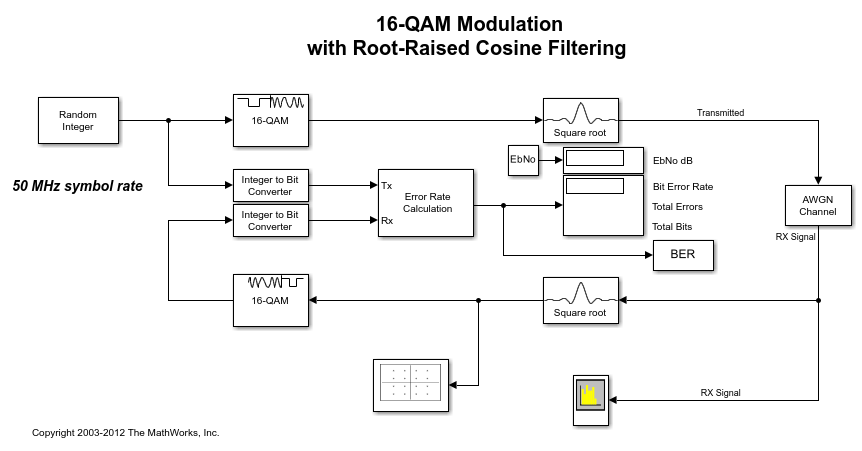
型号RFB_RECEIVER_0.SLX显示了一种通信系统工具箱模型,该模型启发了RF模块构成等效基带库的创建。请注意,这是用于说明目的的简单模型。通信工具箱包括WCDMA,802.11,DVB-S2等更复杂的模型。但是,提出的概念也可以应用于更复杂的模型。
The simple wireless communication system consists of a message source, QAM modulator, root raised cosine filter and an AWGN channel. The model is an executable specification, and is used to validate the specification against requirements and acceptance criteria, "At a BER of 1e-3, the Eb/No must be no greater than 1dB above the theoretical bound for 16QAM."
要验证规格,您可以使用先前保存的Bertool会话文件rfb_receiver_0.ber。To find this file, type the following command at the MATLAB prompt
哪个rfb_receiver_0.ber
使用MATLAB命令打开Bertoolbertool。From the File==>Open Session... dialog box, navigate to the saved sessionrfb_receiver_0.ber。现在,单击蒙特卡洛选项卡,然后单击“运行”按钮。像下面的图一样生成:

Figure 3:BER与EB/没有RF损害的情节
由于实施损失,给定的BER值的EB/NO比理论上的界限高一些。(在当前情况下,主要损失是由于根部提出的余弦过滤器的有限长度引起的。)但是降解在接受标准范围内。
Adding RF Specifications to the Baseline Model
打开('rfb_receiver_1.slx')
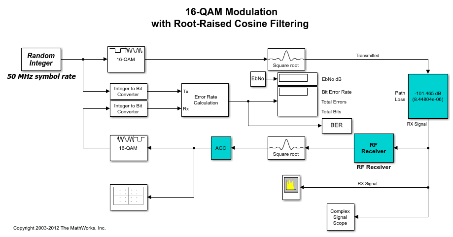
让我们详细说明基线模型,并使用RF模块组件通过其他细化来查看其如何变化。第一步是用路径损耗块替换AWGN块(在青色中的前图中显示);这将降低接近范围值末端的信号级别。将单位功率(1W)降低到给定的EB/NO(也包括在DB中)所需的路径损失(以DB为单位)是:
path_loss = 10*log10(k*T_ref*B*M) + EbNo + NF
wherek是Boltzmann的常数(〜1.38e-23 J/K),t_ref是IEEE®标准噪声参考温度(290K),Bis the noise bandwidth (~50 MHz in this case), andNFis the receiver noise figure in dB.
接下来,包括青色色的RF接收器子系统和AGC块。AGC块是使用解调器所需的现实信号水平的结果。
RF接收器子系统检查了
打开('rfb_receiver_1.slx')open_system('rfb_receiver_1/rf接收器')

Now examine the RF Receiver subsystem, which is a cascaded model of a super heterodyne receiver. The receiver uses blocks from the RF Blockset Equivalent Baseband library. The Simulink signal enters the RF domain through a gateway "Input Port" block. Notice that the connectors after the gateway are different. The standard Simulink arrows have been replaced with RF connection lines. This is to remind us that RF signals are bidirectional. The receiver is a cascade of components each represented as a 2-port network: a filter, a LNA, a mixer, and an IF strip. The Output Port, in this case, is not only the gateway back to Simulink but also represents an ideal quadrature down conversion mixer. Here is a framework or architecture for a receiver that is not yet designed. An executable specification for the RF engineer has been created. Each stage of the RF subsystem includes a budget for the overall gain, noise and nonlinearities, as shown in the following figure.

Figure 4:放大器块参数的规范
作为预算的一个例子,请考虑上图中的前端滤镜。S-参数使用GainVec数组的第一个元素在单个频点上指定,该元素使用该元素使用该数组,该元素使用该元素使用该数组Postloadfcn*在回调模型属性选项卡panel. Each element of the array refers to a stage, so the index 1 refers to the first stage. Values for OIP3, on the Nonlinearity data tab, and for Noise Figure, on the Noise data tab, are similarly specified.

图5:复杂基带等效模拟参数的规范
Now open the Input Port block. This port contains parameters that apply to the overall RF subsystem. A narrowband modeling approach is used to capture the in-band effects that impact downstream signal processing blocks. The range of frequencies is specified through theCenter frequency参数,Sample timeparameter (which is 1/Bandwidth), and the有限脉冲响应滤波器长度参数(这是在建模RF组件中使用的脉冲响应过滤器的长度)。更长的长度域滤波器将在指定的带宽内提供更优质的频域分辨率。要在第一个组件的输入中对不匹配进行建模,此处还指定了源阻抗。注意“添加噪声”复选框。要在模拟中包括噪声,必须选择此“添加噪声”复选框。
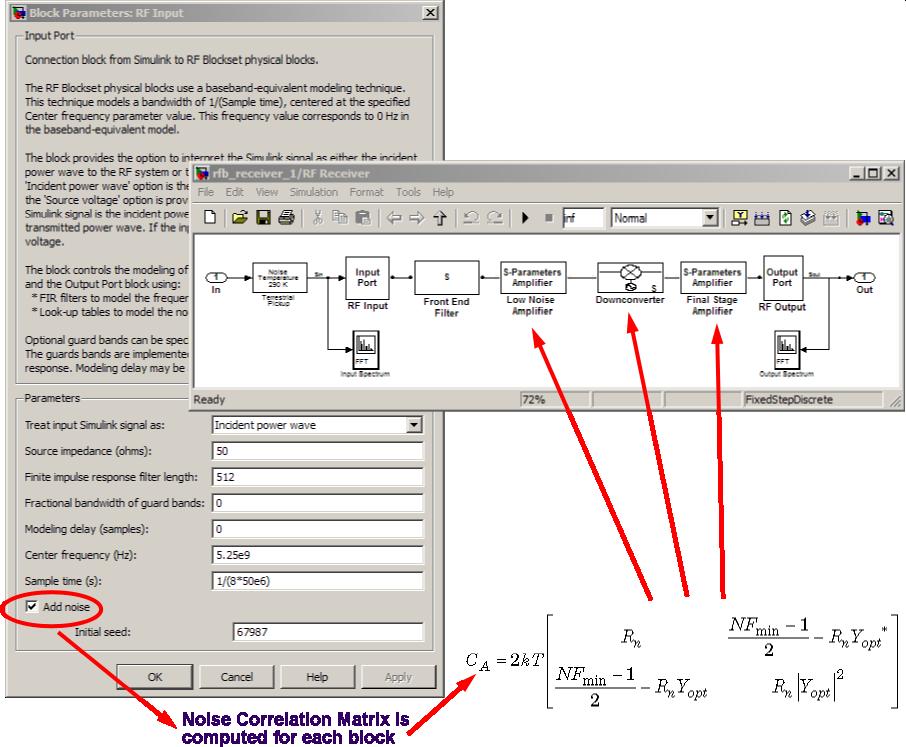
Figure 6:使用RF区块等效基带库进行噪声建模
The AWGN block models overall noise as a signal-to-noise ratio. By contrast, blocks from the RF Blockset Equivalent Baseband library model noise by adding the noise contribution of each block individually. For each block, the noise is modeled using an appropriate formulation determined by the set of noise parameters supplied for that block. Once the noise for each block is calculated, the overall system noise model is developed. This overall model includes the position of each block in the cascade (i.e., includes the gain of the subsequent stages).

Figure 7:BER versus Eb/No plot with RF impairments
Plots of BER versus Eb/No comparing the theoretical, Baseline and Baseline with RF impairments models are given in Figure 7. This is a simple illustration of the convenience afforded by the Model-Based Design methodology. At this point in the process, an executable specification has been developed. This specification will be used by teams to design their subsystems. In the case of the RF subsystem, the abstract RF blocks will be replaced by discrete components. As each RF block is realized, its effect on the system's design criteria can be assessed.
bdclose('rfb_receiver_0');bdclose('rfb_receiver_1');