Archimedean Spiral Design Investigation
该示例将阿基米螺旋天线[1]中发表的结果与使用螺旋天线的工具箱模型获得的结果进行了比较。两臂的阿基赛马螺旋天线(r = R ) can be regarded as a dipole, the arms of which have been wrapped into the shape of an Archimedean spiral. This idea came from Edwin Turner around 1954.
阿基赛马螺旋天线参数
Archimedean螺旋天线可以归类为frequency-independent antenna从某种意义上说,在整个带宽中,其输入阻抗和增益几乎保持恒定。在低频率下,辐射区位于螺旋的最外部,同时在高频处,它在中心附近。因此,螺旋天线的最低截止频率与其外半径有关,最高的截止频率与其内半径有关。这意味着天线的带宽可能非常大,仅取决于尺寸和打印精度。以下是给出的螺旋的尺寸[1]在米中。
Ro = 50e-3; Ri = 5.5e-3; turns = 4;
Create and View Archimedean Spiral Antenna
Create an Archimedean spiral antenna using the parameters defined.
sp = spiralarchimedean('Turns',turns,“ Innerradius”,Ri,'OuterRadius',Ro); figure; show(sp);

Impedance Behavior of Archimedean Spiral Antenna
The impedance behavior of the spiral antenna shows multiple resonances at the low frequency band, before achieving a relatively constant resistance and reactance behavior. To capture these resonances we split the entire frequency band into two subbands. In the lower-frequency band, we sample with a finer spacing, while at the higher frequencies we opt for coarser spacing.
NF1 = 20;NF2 = 6;fband1 = linspace(0.8e9,1.4e9,nf1);fband2 = linspace(1.4e9,2.5e9,nf2);freq = unique([Fband1,fband2]);图;阻抗(SP,FREQ);

Reflection Coefficient
可以使用Booker的Babinet原理扩展补充结构的原理[2],可以获得该螺旋天线的输入阻抗。对于自由空间中的天线,其输入阻抗等于60 = 188.5 。该值非常接近在上面所见图中较高频率下观察到的阻抗的值。反射系数使用188的参考阻抗计算 。From the plot below it is seen that the present antenna is well matched for frequencies higher than 1.1 GHz.
S = sparameters (sp,频率,188);图;rfplot(年代);标题('Reflection Coefficient');

This matched frequency is higher than the approximate theoretical result of 0.96 GHz [1] since the current still reaches spiral tips as seen in the computational figure that follows.
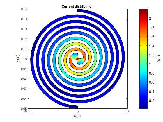
Current Distribution
The surface current distribution at low frequencies is:
图;current(sp, 0.85e9); view(0,90);

At higher frequencies, surface currents decay long before reaching the spiral tips. This results in a better matching.
图;current(sp, 1.9e9); view(0,90);
轴向比
The current distribution presents a 180-degree rotational symmetry, which produces a circularly polarized radiated wave. The plot below shows the axial ratio at broadside of the spiral antenna. Observe that the spiral antenna achieves a good circular polarization for frequencies higher than 1.4 GHz.
freq = 0.8e9:100e6:2.5e9; AR = zeros(size(freq));form=1:numel(freq) AR(m) = axialRatio(sp, freq(m), 0, 90);end图;plot(freq, AR); grid上;轴([0.8E9 2.5E9 0 10]);Xlabel('Frequency (Hz)');ylabel('Axial ratio (dB)');标题('Axial Ratio of Archimedean Spiral Antenna at Boresight');

Discussion on the Results
论文[1]designs an Archimedean spiral antenna and compares its performance to theoretical results as well as to the commercially available EM solvers. The results obtained using the Antenna Toolbox™ match very well with the results presented in [1].
Reference
[1]以色列Hinostroza,“概念de Reseaux大型天线螺旋螺旋”,其他,Supelec,2013年,2013年,第58-62页。在线网址:https://tel.archives-ouvertes.fr/file/index/docid/830469/filename/Hinostroza_Israel_final_final_thesis_2013.pdf
[2] C. A. Balanis, Antenna Theory. Analysis and Design, Wiley, New York, 3rd Edition, 2005.
See Also
You can also select a web site from the following list:
Americas
- AméricaLatina(Español)
- Canada(English)
- United States(English)
欧洲
- Belgium(English)
- 丹麦(English)
- Deutschland(德意志)
- España(Español)
- Finland(English)
- 法国(Français)
- 爱尔兰(English)
- Italia(Italiano)
- Luxembourg(English)
- Netherlands(English)
- 挪威(English)
- Österreich(德意志)
- Portugal(English)
- Sweden(English)
- Switzerland
- United Kingdom(English)