Programmable FIR Filter for FPGA
此示例显示如何为硬件实现可编程FIR筛选器。您可以使用主机接口将系数加载到内部寄存器中来将过滤器编程到所需的响应。
In this example, we will implement a bank of filters, each having different responses, on a chip. If all of the filters have a direct-form FIR structure, and the same length, then we can use a host interface to load the coefficients for each response to a register file when needed.
This design adds latency of a few cycles before the input samples can be processed with the loaded coefficients. However, it has the advantage that the same filter hardware can be programmed with new coefficients to obtain a different filter response. This saves chip area, as otherwise each filter would be implemented separately on the chip.
Model Programmable FIR Filter
Consider two FIR filters, one with a lowpass response and the other with a highpass response. The coefficients are specified by using the Model Properties>Callbacks>InitFcn function.

TheProgrammable FIR via Registersblock loads the lowpass coefficients from the主机行为模型, and processes the input chirp samples first. Then the block loads the highpass coefficients and processes the same chirp samples again.
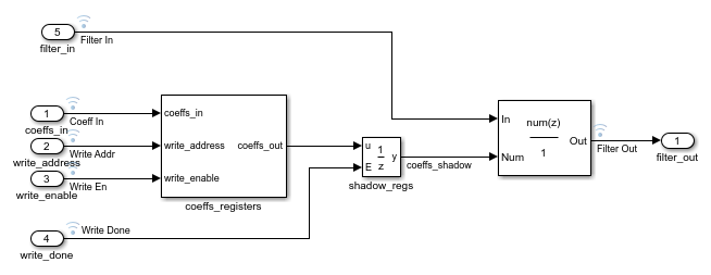
Thecoeffs_registersblock loads the coefficients into internal registers when thewrite_enable信号很高。The shadow registers are updated from the coefficients registers when thewrite_done.信号很高。影子寄存器能够通过滤波器实体同时加载和处理数据。块在处理最后几个输入样本的同时加载第二组系数。
This model is configured to use a fully parallel architecture for the Discrete FIR Filter block. You can also choose serial architectures from theHDL块属性menu.
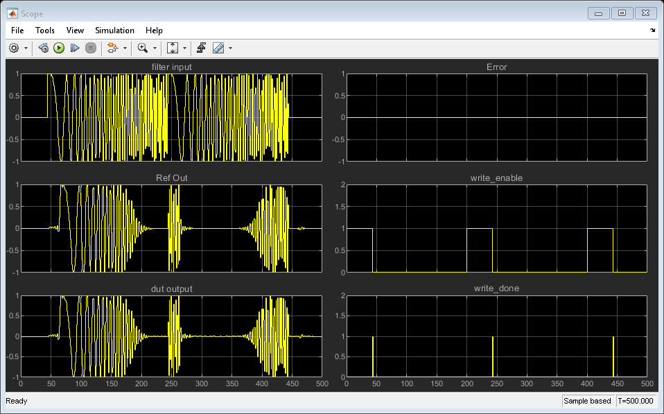
Simulink® Simulation Results
要将测试(DUT)与参考滤波器进行比较,请打开范围并运行示例模型。
Using the Logic Analyzer
You can also view the signals in the Logic Analyzer. The Logic Analyzer enables you to view multiple signals in one window. It also makes it easy to spot the transitions in the signals.
Launch the Logic Analyzer from the model's toolbar.

The signals of interest -- input coefficients, write address, write enable, write done, filter in, filter out, reference out, and error have been added to the Logic Analyzer for observation.

The Logic Analyzer display can also be controlled on a per-wave or per-divider basis. To modify an individual wave or divider, select a wave or divider and then click on the "Wave" tab. A useful mode of visualization in the Logic Analyzer is the Analog format.

有关逻辑分析仪的更多信息,请参阅Logic Analyzerdocumentation.
Generate HDL Code and Test Bench
You must have an HDL Coder™ license to generate HDL code for this example model. Use this command to generate HDL code.
systemname = [modelname'/Programmable FIR via Registers']; makehdl(systemname);
使用此命令生成测试台,该测试台与模拟模拟行为的HDL仿真结果进行比较。金宝appmakehdltb(systemname);
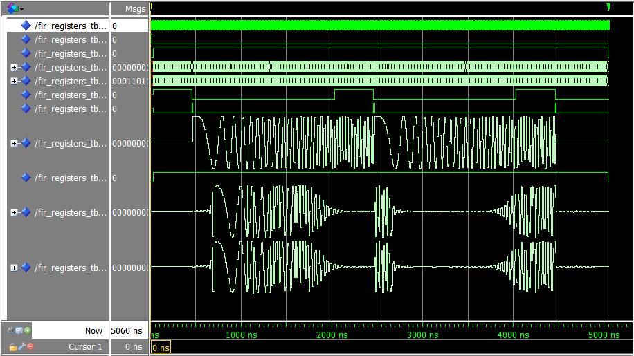
ModelSim™ Simulation Results
The following figure shows the ModelSim HDL simulator after running the generated .do file scripts for the test bench. Compare the ModelSim result with the Simulink result as plotted before.
Select a Web Site
Choose a web site to get translated content where available and see local events and offers. Based on your location, we recommend that you select:.
Selectweb siteYou can also select a web site from the following list:
Americas
- América拉丁(Español)
- Canada(English)
- United States(English)
Europe
- Belgium(English)
- 丹麦(English)
- Deutschland(Deutsch)
- España(Español)
- Finland(English)
- 法国(Français)
- 爱尔兰(English)
- Italia(意大利语)
- Luxembourg(English)
- 荷兰(English)
- 挪威(English)
- Österreich(Deutsch)
- Portugal(English)
- Sweden(English)
- Switzerland
- United Kingdom(English)