Main Content

Subband Phase Shift Beamformer

Subband phase shift beamformer

  • Subband Phase Shift Beamformer block

Libraries:
Phased Array System Toolbox / Beamforming

Description

TheSubband Phase Shift Beamformerblock performs delay-and-sum beamforming in the frequency domain. The signal is divided into frequency subbands. In each subband, a phase shift at the subband center frequency approximates the time delay. The resulting subband signals are summed to form the frequency-domain output signal and then converted to the time domain.

Ports

Input

expand all

Input signal, specified as anM-by-Nmatrix, whereMis the number of samples in the data, andNis the number of array elements.

The size of the first dimension of the input matrix can vary to simulate a changing signal length. A size change can occur, for example, in the case of a pulse waveform with variable pulse repetition frequency.

Data Types:double
Complex Number Support:Yes

Beamforming direction, specified as a2-by-Lreal-valued matrix, whereLis the number of beamforming directions. Each column takes the form of[AzimuthAngle;ElevationAngle]. Angle units are in degrees. The azimuth angle must lie between –180° and 180°, inclusive, and the elevation angle must lie between –90° and 90°, inclusive. Angles are defined with respect to the local coordinate system of the array.

Dependencies

To enable this port, set theSource of beamforming directionparameter toInput port.

Data Types:double

Output

expand all

Beamformed output, returned as anM-by-Lcomplex-valued matrix. The quantityMis the number of signal samples andLis the number of desired beamforming directions specified by theBeamforming directionparameter or from theAngport.

Data Types:double
Complex Number Support:Yes

Subband center frequencies, returned asK-by-1 real-valued column vector. The quantityKis the number of subbands specified by theNumber of subbandsproperty.

Dependencies

To enable this port, select theEnable subband center frequencies outputcheckbox.

Data Types:double

Beamformed weights, returned as anN-by-Lcomplex-valued matrix. The quantityNis the number of array elements. When theSpecify sensor array asparameter is set toPartitioned arrayorReplicated subarray,Nrepresents the number of subarrays.Lis the number of desired beamforming directions specified in theAngport or by theBeamforming direction (deg)property. There is one set of weights for each beamforming direction.

Dependencies

To enable this port, select theEnable weights outputcheckbox.

Data Types:double
Complex Number Support:Yes

Parameters

expand all

Main tab

Signal propagation speed, specified as a real-valued positive scalar. The default value of the speed of light is the value returned byphysconst('LightSpeed'). Units are in meters per second.

Example:3e8

Data Types:double

System operating frequency, specified as a positive scalar. Units are in Hz.

Select this parameter to inherit the sample rate from upstream blocks. Otherwise, specify the sample rate using theSample rate (Hz)parameter.

Data Types:Boolean

Specify the signal sampling rate as a positive scalar. Units are in Hz.

Dependencies

To enable this parameter, clear theInherit sample ratecheck box.

Data Types:double

Number of processing subbands, specified as a positive integer.

Example:128

Source of beamforming direction, specified asPropertyorInput port. When you setSource of beamforming directiontoProperty, you then set the direction using theBeamforming direction (deg)parameter. When you selectInput port, the direction is determined by the input to theAngport.

Beamforming directions, specified as a2-by-Lreal-valued matrix, whereLis the number of beamforming directions. Each column takes the form[AzimuthAngle;ElevationAngle]. Angle units are in degrees. The azimuth angle must lie between –180° and 180°. The elevation angle must lie between –90° and 90°. Angles are defined with respect to the local coordinate system of the array.

Dependencies

To enable this parameter, set theSource of beamforming directionparameter toProperty.

Select this check box to obtain the beamformer weights from the output port,W.

Select this check box to obtain the center frequencies of each subband via the output port,Freq.

Block simulation, specified asInterpreted ExecutionorCode Generation. If you want your block to use the MATLAB®interpreter, chooseInterpreted Execution. If you want your block to run as compiled code, chooseCode Generation. Compiled code requires time to compile but usually runs faster.

Interpreted execution is useful when you are developing and tuning a model. The block runs the underlying System object™ in MATLAB. You can change and execute your model quickly. When you are satisfied with your results, you can then run the block usingCode Generation. Long simulations run faster with generated code than in interpreted execution. You can run repeated executions without recompiling, but if you change any block parameters, then the block automatically recompiles before execution.

This table shows how theSimulate usingparameter affects the overall simulation behavior.

When the Simulink®model is inAcceleratormode, the block mode specified usingSimulate usingoverrides the simulation mode.

Acceleration Modes

Block Simulation Simulation Behavior
Normal Accelerator Rapid Accelerator
Interpreted Execution The block executes using the MATLAB interpreter. The block executes using the MATLAB interpreter. Creates a standalone executable from the model.
Code Generation The block is compiled. All blocks in the model are compiled.

为米ore information, seeChoosing a Simulation Mode(Simulink).

Programmatic Use

Block Parameter:SimulateUsing
Type:enum
Values:Interpreted Execution,Code Generation
Default:Interpreted Execution
Sensor Arrays Tab

Method to specify array, specified asArray (no subarrays)orMATLAB expression.

  • Array (no subarrays)— use the block parameters to specify the array.

  • Partitioned array— use the block parameters to specify the array.

  • Replicated subarray— use the block parameters to specify the array.

  • MATLAB expression— create the array using a MATLAB expression.

MATLAB expression used to create an array, specified as a valid Phased Array System Toolbox array System object.

Example:phased.URA('Size',[5,3])

Dependencies

To enable this parameter, setSpecify sensor array astoMATLAB expression.

Element Parameters

Antenna or microphone type, specified as one of the following:

  • Isotropic Antenna

  • Cosine Antenna

  • Custom Antenna

  • Omni Microphone

  • Custom Microphone

Specify the operating frequency range of the antenna or microphone element as a 1-by-2 row vector in the form[LowerBound,UpperBound]. The element has no response outside this frequency range. Frequency units are in Hz.

Dependencies

To enable this parameter, setElement typetoIsotropic Antenna,Cosine Antenna, orOmni Microphone.

一个指定的频率设置天线d microphone frequency responses as a 1-by-Lrow vector of increasing real values. The antenna or microphone element has no response outside the frequency range specified by the minimum and maximum elements of this vector. Frequency units are in Hz.

Dependencies

To enable this parameter, setElement typetoCustom AntennaorCustom Microphone. UseFrequency responses (dB)to set the responses at these frequencies.

Select this check box to baffle the back response of the element. When back baffled, the responses at all azimuth angles beyond ±90° from broadside are set to zero. The broadside direction is defined as 0° azimuth angle and 0° elevation angle.

Dependencies

To enable this check box, setElement typetoIsotropic AntennaorOmni Microphone.

Specify the exponents of the cosine pattern as a nonnegative scalar or a real-valued 1-by-2 matrix of nonnegative values. WhenExponent of cosine patternis a 1-by-2 vector, the first element is the exponent in the azimuth direction and the second element is the exponent in the elevation direction. When you set this parameter to a scalar, both the azimuth direction and elevation direction cosine patterns are raised to the same power.

Dependencies

To enable this parameter, setElement typetoCosine Antenna.

Frequency response of a custom antenna or custom microphone for the frequencies defined by theOperating frequency vector (Hz)parameter. The dimensions ofFrequency responses (dB)must match the dimensions of the vector specified by theOperating frequency vector (Hz)parameter.

Dependencies

To enable this parameter, setElement typetoCustom AntennaorCustom Microphone.

Coordinate system of custom antenna pattern, specifiedaz-elorphi-theta. When you specifyaz-el, use theAzimuth angles (deg)andElevations angles (deg)parameters to specify the coordinates of the pattern points. When you specifyphi-theta, use thePhi angles (deg)andTheta angles (deg)parameters to specify the coordinates of the pattern points.

Dependencies

To enable this parameter, setElement typetoCustom Antenna.

Specify the azimuth angles at which to calculate the antenna radiation pattern as a 1-by-Prow vector.Pmust be greater than 2. Azimuth angles must lie between –180° and 180°, inclusive, and be in strictly increasing order.

Dependencies

To enable this parameter, set theElement typeparameter toCustom Antennaand theInput Pattern Coordinate Systemparameter toaz-el.

Specify the elevation angles at which to compute the radiation pattern as a 1-by-Qvector.Qmust be greater than 2. Angle units are in degrees. Elevation angles must lie between –90° and 90°, inclusive, and be in strictly increasing order.

Dependencies

To enable this parameter, set theElement typeparameter toCustom Antennaand theInput Pattern Coordinate Systemparameter toaz-el.

Phi angles of points at which to specify the antenna radiation pattern, specify as a real-valued 1-by-Prow vector.Pmust be greater than 2. Angle units are in degrees. Phi angles must lie between 0° and 360° and be in strictly increasing order.

Dependencies

To enable this parameter, set theElement typeparameter toCustom Antennaand theInput Pattern Coordinate Systemparameter tophi-theta.

Theta angles of points at which to specify the antenna radiation pattern, specify as a real-valued 1-by-Qrow vector.Qmust be greater than 2. Angle units are in degrees. Theta angles must lie between 0° and 360° and be in strictly increasing order.

Dependencies

To enable this parameter, set theElement typeparameter toCustom Antennaand theInput Pattern Coordinate Systemparameter tophi-theta.

Magnitude of the combined antenna radiation pattern, specified as aQ-by-Pmatrix or aQ-by-P-by-Larray.

  • When theInput Pattern Coordinate Systemparameter is set toaz-el,Qequals the length of the vector specified by theElevation angles (deg)parameter andPequals the length of the vector specified by theAzimuth angles (deg)parameter.

  • When theInput Pattern Coordinate Systemparameter is set tophi-theta,Qequals the length of the vector specified by theTheta Angles (deg)parameter andPequals the length of the vector specified by thePhi Angles (deg)parameter.

The quantityLequals the length of theOperating frequency vector (Hz).

  • If this parameter is aQ-by-Pmatrix, the same pattern is applied toall中指定的频率Operating frequency vector (Hz)parameter.

  • If the value is aQ-by-P-by-Larray, eachQ-by-Ppage of the array specifies a pattern for thecorrespondingfrequency specified in theOperating frequency vector (Hz)parameter.

Dependencies

To enable this parameter, setElement typetoCustom Antenna.

Phase of the combined antenna radiation pattern, specified as aQ-by-Pmatrix or aQ-by-P-by-Larray.

  • When theInput Pattern Coordinate Systemparameter is set toaz-el,Qequals the length of the vector specified by theElevation angles (deg)parameter andPequals the length of the vector specified by theAzimuth angles (deg)parameter.

  • When theInput Pattern Coordinate Systemparameter is set tophi-theta,Qequals the length of the vector specified by theTheta Angles (deg)parameter andPequals the length of the vector specified by thePhi Angles (deg)parameter.

The quantityLequals the length of theOperating frequency vector (Hz).

  • If this parameter is aQ-by-Pmatrix, the same pattern is applied toall中指定的频率Operating frequency vector (Hz)parameter.

  • If the value is aQ-by-P-by-Larray, eachQ-by-Ppage of the array specifies a pattern for thecorrespondingfrequency specified in theOperating frequency vector (

Dependencies

To enable this parameter, setElement typetoCustom Antenna.

Select this check box to rotate the antenna element pattern to align with the array normal. When not selected, the element pattern is not rotated.

When the antenna is used in an antenna array and theInput Pattern Coordinate Systemparameter isaz-el, selecting this check box rotates the pattern so that thex-axis of the element coordinate system points along the array normal. Not selecting uses the element pattern without the rotation.

When the antenna is used in an antenna array andInput Pattern Coordinate Systemis set tophi-theta, selecting this check box rotates the pattern so that thez-axis of the element coordinate system points along the array normal.

Use the parameter in conjunction with theArray normalparameter of theURAandUCAarrays.

Dependencies

To enable this parameter, setElement typetoCustom Antenna.

Polar pattern microphone response frequencies, specified as a real scalar, or a real-valued, 1-by-Lvector. The response frequencies lie within the frequency range specified by theOperating frequency vector (Hz)vector.

Dependencies

To enable this parameter, setElement typeset toCustom Microphone.

Specify the polar pattern response angles, as a 1-by-Pvector. The angles are measured from the central pickup axis of the microphone and must be between –180° and 180°, inclusive.

Dependencies

To enable this parameter, setElement typetoCustom Microphone.

Specify the magnitude of the custom microphone element polar patterns as anL-by-Pmatrix.Lis the number of frequencies specified inPolar pattern frequencies (Hz).Pis the number of angles specified inPolar pattern angles (deg). Each row of the matrix represents the magnitude of the polar pattern measured at the corresponding frequency specified inPolar pattern frequencies (Hz)and all angles specified inPolar pattern angles (deg). The pattern is measured in the azimuth plane. In the azimuth plane, the elevation angle is 0° and the central pickup axis is 0° degrees azimuth and 0° degrees elevation. The polar pattern is symmetric around the central axis. You can construct the microphone response pattern in 3-D space from the polar pattern.

Dependencies

To enable this parameter, setElement typetoCustom Microphone.

Array Parameters

Array geometry, specified as one of

  • ULA— Uniform linear array

  • URA— Uniform rectangular array

  • UCA— Uniform circular array

  • Conformal Array— arbitrary element positions

The number of array elements for ULA or UCA arrays, specified as an integer greater than or equal to 2.

When you setSpecify sensor array astoReplicated subarray, this parameter applies to each subarray.

Dependencies

To enable this parameter, setGeometrytoULAorUCA.

Spacing between adjacent array elements:

  • ULA — specify the spacing between two adjacent elements in the array as a positive scalar.

  • URA — specify the spacing as a positive scalar or a 1-by-2 vector of positive values. IfElement spacing (m)is a scalar, the row and column spacings are equal. IfElement spacing (m)is a vector, the vector has the form[SpacingBetweenArrayRows,SpacingBetweenArrayColumns].

  • When you setSpecify sensor array astoReplicated subarray, this parameter applies to each subarray.

Dependencies

To enable this parameter, setGeometrytoULAorURA.

Linear axis direction of ULA, specified asy,x, orz. All ULA array elements are uniformly spaced along this axis in the local array coordinate system.

Dependencies

  • To enable this parameter, setGeometrytoULA.

  • This parameter is also enabled when the block only supports ULA arrays.

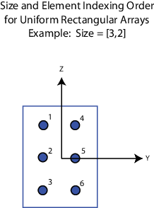
Dimensions of a URA array, specified as a positive integer or 1-by-2 vector of positive integers.

  • IfArray sizeis a 1-by-2 vector, the vector has the form[NumberOfArrayRows,NumberOfArrayColumns].

  • IfArray sizeis an integer, the array has the same number of rows and columns.

  • When you setSpecify sensor array astoReplicated subarray, this parameter applies to each subarray.

For a URA, array elements are indexed from top to bottom along the leftmost column, and then continue to the next columns from left to right. In this figure, theArray sizevalue of[3,2]创建一个数组有三排和两列.

Dependencies

To enable this parameter, setGeometrytoURA.

Lattice of URA element positions, specified asRectangularorTriangular.

  • Rectangular— Aligns all the elements in row and column directions.

  • Triangular— Shifts the even-row elements of a rectangular lattice toward the positive row-axis direction. The displacement is one-half the element spacing along the row dimension.

Dependencies

To enable this parameter, setGeometrytoURA.

Array normal direction, specified asx,y, orz.

Elements of planar arrays lie in a plane orthogonal to the selected array normal direction. Element boresight directions point along the array normal direction.

Array Normal Parameter Value Element Positions and Boresight Directions
x Array elements lie in theyz-plane. All element boresight vectors point along thex-axis.
y Array elements lie in thezx-plane. All element boresight vectors point along they-axis.
z Array elements lie in thexy-plane. All element boresight vectors point along thez-axis.

Dependencies

To enable this parameter, setGeometrytoURAorUCA.

Radius of UCA array, specified as a positive scalar.

Dependencies

To enable this parameter, setGeometrytoUCA.

Positions of the elements in a conformal array, specified as a 3-by-Nmatrix of real values, whereNis the number of elements in the conformal array. Each column of this matrix represents the position[x;y;z]of an array element in the array local coordinate system. The origin of the local coordinate system is(0,0,0). Units are in meters.

When you setSpecify sensor array astoReplicated subarray, this parameter applies to each subarray.

Dependencies

To enable this parameter setGeometrytoConformal Array.

Direction of element normal vectors in a conformal array, specified as a 2-by-1 column vector or a 2-by-Nmatrix.Nindicates the number of elements in the array. For a matrix, each column specifies the normal direction of the corresponding element in the form[azimuth;elevation]with respect to the local coordinate system. The local coordinate system aligns the positivex-axis with the direction normal to the conformal array. If the parameter value is a 2-by-1 column vector, the same pointing direction is used for all array elements.

When you setSpecify sensor array astoReplicated subarray, this parameter applies to each subarray.

You can use theElement positions (m)andElement normals (deg)参数p代表任何安排airs of elements differ by certain transformations. The transformations can combine translation, azimuth rotation, and elevation rotation. However, you cannot use transformations that require rotation about the normal direction.

Dependencies

To enable this parameter, setGeometrytoConformal Array.

Element tapering, specified as a complex-valued scalar or a complex-valued 1-by-Nrow vector. In this vector,Nrepresents the number of elements in the array.

Also known aselement weights, tapers multiply the array element responses. Tapers modify both amplitude and phase of the response to reduce side lobes or steer the main response axis.

IfTaperis a scalar, the same weight is applied to each element. IfTaperis a vector, a weight from the vector is applied to the corresponding sensor element. The number of weights must match the number of elements of the array.

When you setSpecify sensor array astoReplicated subarray, this parameter applies to each subarray.

Specify the subarray selection as anM-by-Nmatrix.Mis the number of subarrays andNis the total number of elements in the array. Each row of the matrix represents a subarray and each entry in the row indicates when an element belongs to the subarray. When the entry is zero, the element does not belong the subarray. A nonzero entry represents a complex-valued weight applied to the corresponding element. Each row must contain at least one nonzero entry.

The phase center of each subarray lies at the subarray geometric center. The subarray geometric center depends on theSubarray definition matrixandGeometryparameters.

Dependencies

To enable this parameter, setSpecify sensor array astoPartitioned array.

Subarray steering method, specified as one of

  • None

  • Phase

  • Time

  • Custom

SelectingPhaseorTimeopens theSteerinput port on theNarrowband Receive Array,Narrowband Transmit Array,Wideband Receive Array,Wideband Transmit Arrayblocks,Constant Gamma Clutter, andGPU Constant Gamma Clutterblocks.

SelectingCustomopens theWSinput port on theNarrowband Receive Array,Narrowband Transmit Array,Wideband Receive Array,Wideband Transmit Arrayblocks,Constant Gamma Clutter, andGPU Constant Gamma Clutterblocks.

Dependencies

To enable this parameter, setSpecify sensor array astoPartitioned arrayorReplicated subarray.

Operating frequency of subarray steering phase shifters, specified as a positive real-valued scalar. Units are Hz.

Dependencies

To enable this parameter, setSensor arraytoPartitioned arrayorReplicated subarrayand setSubarray steering methodtoPhase.

Subarray steering phase shift quantization bits, specified as a non-negative integer. A value of zero indicates that no quantization is performed.

Dependencies

To enable this parameter, setSensor arraytoPartitioned arrayorReplicated subarrayand setSubarray steering methodtoPhase.

Specify the layout of replicated subarrays asRectangularorCustom.

  • When you set this parameter toRectangular, use theGrid sizeandGrid spacingparameters to place the subarrays.

  • When you set this parameter toCustom, use theSubarray positions (m)andSubarray normalsparameters to place the subarrays.

Dependencies

To enable this parameter, setSensor arraytoReplicated subarray

Rectangular subarray grid size, specified as a single positive integer, or a 1-by-2 row vector of positive integers.

IfGrid sizeis an integer scalar, the array has an equal number of subarrays in each row and column. IfGrid sizeis a 1-by-2 vector of the form[NumberOfRows, NumberOfColumns], the first entry is the number of subarrays along each column. The second entry is the number of subarrays in each row. A row is along the localy-axis, and a column is along the localz-axis. The figure here shows how you can replicate a 3-by-2 URA subarray using aGrid sizeof[1,2].

Dependencies

To enable this parameter, setSensor arraytoReplicated subarrayandSubarrays layouttoRectangular.

The rectangular grid spacing of subarrays, specified as a positive, real-valued scalar, a 1-by-2 row vector of positive, real-values, orAuto. Units are in meters.

  • IfGrid spacingis a scalar, the spacing along the row and the spacing along the column is the same.

  • IfGrid spacingis a 1-by-2 row vector, the vector has the form[SpacingBetweenRows,SpacingBetweenColumn]. The first entry specifies the spacing between rows along a column. The second entry specifies the spacing between columns along a row.

  • IfGrid spacingis set toAuto, replication preserves the element spacing of the subarray for both rows and columns while building the full array. This option is available only when you specifyGeometryasULAorURA.

Dependencies

To enable this parameter, setSensor arraytoReplicated subarrayandSubarrays layouttoRectangular.

Positions of the subarrays in the custom grid, specified as a real 3-by-Nmatrix, whereNis the number of subarrays in the array. Each column of the matrix represents the position of a single subarray in the array local coordinate system. The coordinates are expressed in the form[x; y; z]. Units are in meters.

Dependencies

To enable this parameter, setSensor arraytoReplicated subarrayandSubarrays layouttoCustom.

Specify the normal directions of the subarrays in the array. This parameter value is a 2-by-Nmatrix, whereNis the number of subarrays in the array. Each column of the matrix specifies the normal direction of the corresponding subarray, in the form[azimuth;elevation]. Angle units are in degrees. Angles are defined with respect to the local coordinate system.

You can use theSubarray positionsandSubarray normals参数p代表任何安排airs of subarrays differ by certain transformations. The transformations can combine translation, azimuth rotation, and elevation rotation. However, you cannot use transformations that require rotation about the normal.

Dependencies

To enable this parameter, set theSensor arrayparameter toReplicated subarrayand theSubarrays layouttoCustom.

Version History

Introduced in R2014b