systemcomposer.interface.PhysicalDomain
Physical domain inSystem Composer
Description
APhysicalDomainobject describes a physical domain in System Composer™. A physical domain can be used as an owned interface on a port and typed to a physical element on a physical interface.
Creation
Create an owned interface using a physical domain on a port.
model = systemcomposer.createModel('archModel',true); rootArch = get(model,'Architecture');newComponent = addComponent(rootArch,'newComponent');newPort = addPort(newComponent.Architecture,'newCompPort','physical');port = newComponent.getPort('newCompPort');interface = port.createInterface; interface.Domain ='mechanical.rotational.rotational'
Properties
Object Functions
destroy |
Remove model element |
Examples
Build Architecture Models Programmatically
Build an architecture model programmatically using System Composer™.
Build Model
To build a model, add a data dictionary with data interfaces, data elements, a value type, and a physical interface, then add components, ports, and connections. Create a profile with stereotypes and properties and then apply those stereotypes to model elements. Assign an owned interface to a port. After the model is built, you can create custom views to focus on specific considerations. You can also query the model to collect different model elements according to criteria you specify.
Add Components, Ports, Connections, and Interfaces
Create a model and extract its architecture.
model = systemcomposer.createModel("mobileRobotAPI");arch = model.Architecture;
创建一个接口数据字典,并添加一个数据interface. Add a data element to the data interface. Add a value type to the interface data dictionary. Assign the type of the data element to the value type. Add a physical interface and physical element with a physical domain type. Link the data dictionary to the model.
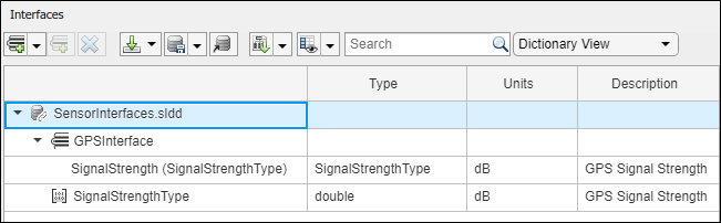
dictionary = systemcomposer.createDictionary("SensorInterfaces.sldd");interface = dictionary.addInterface("GPSInterface");element = interface.addElement("SignalStrength");valueType = dictionary.addValueType("SignalStrengthType",Units="dB",Description="GPS Signal Strength");element.setType(valueType); physicalInterface = dictionary.addPhysicalInterface("PhysicalInterface");physicalElement = addElement(physicalInterface,"ElectricalElement",Type="electrical.electrical");linkDictionary(model,"SensorInterfaces.sldd");
Save the changes to the interface data dictionary.
dictionary.save
Save the model.
model.save
Open the model.
systemcomposer.openModel("mobileRobotAPI");
View the interfaces in the Interface Editor.
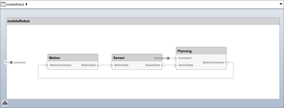
Add components, ports, and connections. Set the physical interface to the physical ports, which you will connect later.
componentSensor = addComponent(arch,"Sensor");sensorPorts = addPort(componentSensor.Architecture,{'MotionData','SensorPower'},{'in','physical'}); sensorPorts(2).setInterface(physicalInterface) componentPlanning = addComponent(arch,"Planning");planningPorts = addPort(componentPlanning.Architecture,{'Command','SensorPower1','MotionCommand'},{'in','physical','out'}); planningPorts(2).setInterface(physicalInterface) componentMotion = addComponent(arch,"Motion");motionPorts = addPort(componentMotion.Architecture,{'MotionCommand','MotionData'},{'in','out'});
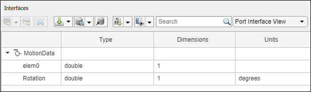
Create an owned interface on the'MotionData'port. Add an owned data element under the owned data interface. Assign the data element "Rotation"to a value type with units set todegrees.
ownedInterface = motionPorts(2).createInterface("DataInterface");ownedElement = ownedInterface.addElement("Rotation");subInterface = ownedElement.createOwnedType(Units="degrees");
View the interfaces in the Interface Editor. Select the'MotionData'port on theMotioncomponent. In the Interface Editor, switch fromDictionary ViewtoPort Interface View.
Connect components with an interface rule and the default name rule. The interface rule connects ports on components that share the same interface. By default, the name rule connects ports on components that share the same name.
c_sensorData = connect(arch,componentSensor,componentPlanning,Rule="interface");c_motionData = connect(arch,componentMotion,componentSensor); c_motionCommand = connect(arch,componentPlanning,componentMotion);
Add and Connect Architecture Port
Add an architecture port on the architecture.
archPort = addPort(arch,"Command","in");
Theconnectcommand requires a component port as an argument. Obtain the component port, then connect.
compPort = getPort(componentPlanning,"Command");c_Command = connect(archPort,compPort);
Save the model.
model.save
Arrange the layout by pressıngCtrl+Shift+Aor using this command.
Simulink.BlockDiagram.arrangeSystem("mobileRobotAPI");
Create and Apply Profile with Stereotypes
Profiles are XML files that can be applied to any model. You can add stereotypes with properties to profiles and then populate the properties with specific values. Along with the built-in analysis capabilities of System Composer, stereotypes help you optimize your system for performance, cost, and reliability.
Create Profile and Add Stereotypes
Create a profile.
profile = systemcomposer.createProfile("GeneralProfile");
Create a stereotype that applies to all element types.
elemSType = addStereotype(profile,"projectElement");
Create stereotypes for different types of components. You can select these types are based on your design needs.
pCompSType = addStereotype(profile,"physicalComponent",AppliesTo="Component");sCompSType = addStereotype(profile,"softwareComponent",AppliesTo="Component");
Create a stereotype for connections.
sConnSType = addStereotype(profile,"standardConn",AppliesTo="Connector");
Add Properties
Add properties to the stereotypes. You can use properties to capture metadata for model elements and analyze nonfunctional requirements. These properties are added to all elements to which the stereotype is applied, in any model that imports the profile.
addProperty(elemSType,'ID',Type="uint8");addProperty(elemSType,'Description',Type="string");addProperty(pCompSType,'Cost',Type="double",Units="USD");addProperty(pCompSType,'Weight',Type="double",Units="g");addProperty(sCompSType,'develCost',Type="double",Units="USD");addProperty(sCompSType,“develTime”,Type="double",Units="hour");addProperty(sConnSType,'unitCost',Type="double"',Units="USD");addProperty(sConnSType,'unitWeight',Type="double",Units="g");addProperty(sConnSType,'length',Type="double",Units="m");
保存配置文件
profile.save;
Apply Profile to Model
Apply the profile to the model.
applyProfile(model,"GeneralProfile");
Apply stereotypes to components. Some components are physical components, while others are software components.
applyStereotype(componentPlanning,"GeneralProfile.softwareComponent") applyStereotype(componentSensor,"GeneralProfile.physicalComponent") applyStereotype(componentMotion,"GeneralProfile.physicalComponent")
Apply the connector stereotype to all connections.
batchApplyStereotype(arch,'Connector',"GeneralProfile.standardConn");
Apply the general element stereotype to all connectors and ports.
batchApplyStereotype(arch,'Component',"GeneralProfile.projectElement");batchApplyStereotype(arch,'Connector',"GeneralProfile.projectElement");
Set properties for each component.
setProperty(componentSensor,'GeneralProfile.projectElement.ID','001');setProperty(componentSensor,'GeneralProfile.projectElement.Description','''Central unit for all sensors''');setProperty(componentSensor,'GeneralProfile.physicalComponent.Cost','200');setProperty(componentSensor,'GeneralProfile.physicalComponent.Weight','450');setProperty(componentPlanning,'GeneralProfile.projectElement.ID','002');setProperty(componentPlanning,'GeneralProfile.projectElement.Description','''Planning computer''');setProperty(componentPlanning,'GeneralProfile.softwareComponent.develCost','20000');setProperty(componentPlanning,'GeneralProfile.softwareComponent.develTime','300');setProperty(componentMotion,'GeneralProfile.projectElement.ID','003');setProperty(componentMotion,'GeneralProfile.projectElement.Description','''Motor and motor controller''');setProperty(componentMotion,'GeneralProfile.physicalComponent.Cost','4500');setProperty(componentMotion,'GeneralProfile.physicalComponent.Weight','2500');
Set the properties of connections to be identical.
connections = [c_sensorData c_motionData c_motionCommand c_Command];fork = 1:length(connections) setProperty(connections(k),'GeneralProfile.standardConn.unitCost','0.2');setProperty(connections(k),'GeneralProfile.standardConn.unitWeight','100');setProperty(connections(k),'GeneralProfile.standardConn.length','0.3');end
Add Hierarchy
Add two components namedControllerandScopeinside theMotioncomponent. Define the ports. Connect the components to the architecture and to each other, applying a connector stereotype. Hierarchy in an architecture diagram creates an additional level of detail that specifies how components behave internally.
motionArch = componentMotion.Architecture; motionController = motionArch.addComponent('Controller');controllerPorts = addPort(motionController.Architecture,{'controlIn','controlOut'},{'in','out'}); controllerCompPortIn = motionController.getPort('controlIn');controllerCompPortOut = motionController.getPort('controlOut');motionScope = motionArch.addComponent('Scope');scopePorts = addPort (motionScope。架构,{'scopeIn','scopeOut'},{'in','out'}); scopeCompPortIn = motionScope.getPort('scopeIn');scopeCompPortOut = motionScope.getPort('scopeOut');c_planningController = connect(motionPorts(1),controllerCompPortIn);
For outport connections, the data element must be specified.
c_planningScope = connect(scopeCompPortOut,motionPorts(2),'DestinationElement',"Rotation");c_planningConnect = connect(controllerCompPortOut,scopeCompPortIn,'GeneralProfile.standardConn');
Save the model.
model.save
Arrange the layout by pressıngCtrl+Shift+Aor using this command.
Simulink.BlockDiagram.arrangeSystem('mobileRobotAPI/Motion');
Create Model Reference
Model references can help you organize large models hierarchically and define architectures or behaviors once that you can then reuse. When a component references another model, any existing ports on the component are removed, and ports that exist on the referenced model will appear on the component.
Create a new System Composer model. Convert theControllercomponent into a reference component to reference the new model. To add additional ports on theControllercomponent, you must update the referenced model"mobileMotion".
referenceModel = systemcomposer.createModel("mobileMotion");referenceArch = referenceModel.Architecture; newComponents = addComponent(referenceArch,"Gyroscope");referenceModel.save linkToModel(motionController,"mobileMotion");

Save the models.
referenceModel.save model.save
Make Variant Component
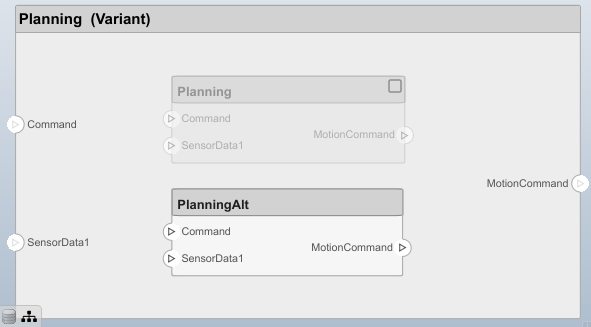
You can convert thePlanningcomponent to a variant component using themakeVariantfunction. The original component is embedded within a variant component as one of the available variant choices. You can design other variant choices within the variant component and toggle the active choice. Variant components allow you to choose behavioral designs programmatically in an architecture model to perform trade studies and analysis.
[variantComp,choice1] = makeVariant(componentMotion);
Add an additional variant choice named MotionAlt. The second argument defines the name, and the third argument defines the label. The label identifies the choice. The active choice is controlled by the label.
choice2 = addChoice(variantComp,{'MotionAlt'},{'MotionAlt'});
Create the necessary ports on MotionAlt.
motionAltPorts = addPort(choice2.Architecture,{'MotionCommand','MotionData'},{'in','out'});
Make MotionAltthe active variant.
setActiveChoice(variantComp,'MotionAlt')
Arrange the layout by pressıngCtrl+Shift+Aor using this command.
Simulink.BlockDiagram.arrangeSystem('mobileRobotAPI/Planning');

Save the model.
model.save
Clean Up
Run this script to remove generated artifacts before you run this example again.
cleanUpArtifacts
More About
Version History
You can also select a web site from the following list:
Americas
- América Latina(Español)
- Canada(English)
- United States(English)
Europe
- Belgium(English)
- Denmark(English)
- Deutschland(Deutsch)
- España(Español)
- Finland(English)
- France(Français)
- Ireland(English)
- Italia(Italiano)
- Luxembourg(English)
- Netherlands(English)
- Norway(English)
- Österreich(Deutsch)
- Portugal(English)
- Sweden(English)
- Switzerland
- United Kingdom(English)