systemcomposer.arch.BaseConnector
架构模型中的所有连接器
描述
一个BaseConnector对象不能被构造。创建systemcomposer.arch.Connector或者一个systemcomposer.arch.PhysicalConnector对象。的systemcomposer.arch.BaseConnector类派生自systemcomposer.arch.Element.
属性
对象的功能
applyStereotype |
将原型应用到体系结构模型元素 |
getStereotypes |
在架构模型的元素上应用原型 |
removeStereotype |
从模型元素中删除原型 |
getProperty |
获取应用于元素的原型对应的属性值 |
setProperty |
设置应用于元素的原型对应的属性值 |
getPropertyValue |
获取建筑属性的价值 |
getEvaluatedPropertyValue |
从元素中获取属性的评估值 |
getStereotypeProperties |
获取元素的原型属性名 |
getDestinationElement |
获取在连接的目标端口上选择的数据元素 |
getSourceElement |
获取在连接的源端口上选择的数据元素 |
hasStereotype |
查找元素是否应用了原型 |
hasProperty |
查找元素是否具有属性 |
摧毁 |
删除模型元素 |
例子
以编程方式构建体系结构模型
使用System Composer™以编程方式构建体系结构模型。
构建模型
要构建模型,需要添加一个数据字典,其中包含数据接口、数据元素、值类型和物理接口,然后添加组件、端口和连接。创建一个带有构造型和属性的概要文件,然后将这些构造型应用于模型元素。将拥有的接口分配给端口。在构建模型之后,您可以创建自定义视图来关注特定的考虑事项。您还可以根据您指定的条件查询模型来收集不同的模型元素。
添加组件、端口、连接和接口
创建一个模型并提取其架构。
模型= systemcomposer.createModel(“mobileRobotAPI”);arch = model.Architecture;
创建接口数据字典,添加数据接口。向数据接口添加数据元素。向接口数据字典添加值类型。将数据元素的类型指定为值类型。使用物理域类型添加物理接口和物理元素。将数据字典链接到模型。
字典= systemcomposer.createDictionary(“SensorInterfaces.sldd”);interface = dictionary.addInterface(“GPSInterface”);元素= interface.addElement(“SignalStrength”);valueType = dictionary.addValueType(“SignalStrengthType”单位=“数据库”、描述=“GPS信号强度”);element.setType (valueType);physicalInterface = dictionary.addPhysicalInterface(“PhysicalInterface”);物理元素= addElement(物理接口,“ElectricalElement”类型=“electrical.electrical”);linkDictionary(模型,“SensorInterfaces.sldd”);
将更改保存到接口数据字典中。
dictionary.save
保存模型。
model.save
打开模型。
systemcomposer.openModel (“mobileRobotAPI”);
在“接口编辑器”中查看接口。

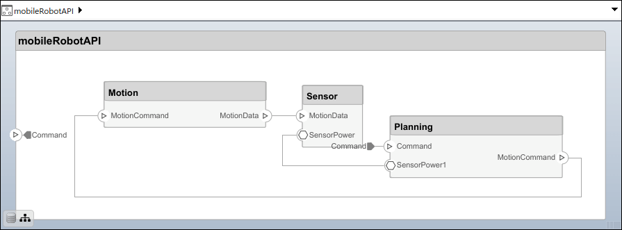
添加组件、端口和连接。将物理接口设置为物理端口,稍后将进行连接。
componentSensor = addComponent(arch,“传感器”);sensorPorts = addPort(componentSensor。架构,{“MotionData”,“SensorPower”},{“在”,“物理”});sensorPorts(2).setInterface(physicalInterface) componentPlanning = addComponent(arch,“计划”);planningPorts = addPort(componentPlanning。架构,{“命令”,“SensorPower1”,“MotionCommand”},{“在”,“物理”,“出”});planningPorts(2).setInterface(physicalInterface) componentMotion = addComponent(arch,“运动”);motionPorts = addPort(componentMotion.)架构,{“MotionCommand”,“MotionData”},{“在”,“出”});
上创建一个拥有的接口“MotionData”端口。在所属数据接口下添加所属数据元素。分配数据元素"旋转”到单位设置为的值类型度.
ownedInterface = motionPorts(2).createInterface(“DataInterface”);ownedElement = ownedInterface.addElement(“旋转”);subInterface = ownedElement.createOwnedType(Units=“度”);
在“接口编辑器”中查看接口。选择“MotionData”上的端口运动组件。在“接口编辑器”中,从字典视图来端口接口视图.

使用接口规则和默认名称规则连接组件。接口规则连接的是共用一个接口的组件上的端口。缺省情况下,名称规则连接的是名称相同的组件端口。
c_sensorData = connect(arch,componentSensor,componentPlanning,Rule=“界面”);c_motionData = connect(arch,componentMotion,componentSensor);c_motionCommand = connect(arch,componentPlanning,componentMotion);
添加和连接体系结构端口
在架构上添加架构端口。
archPort = addPort(arch,“命令”,“在”);
的连接命令需要一个组件端口作为参数。获取组件端口,然后连接。
compPort = getPort(componentPlanning,“命令”);c_Command = connect(archPort,compPort);
保存模型。
model.save
按下排列布局Ctrl + Shift +一个或者使用此命令。
金宝appSimulink.BlockDiagram.arrangeSystem (“mobileRobotAPI”);
使用构造型创建并应用配置文件
概要文件是可以应用于任何模型的XML文件。您可以将带有属性的构造型添加到概要文件中,然后用特定的值填充属性。与System Composer的内置分析功能一起,原型可以帮助您优化系统的性能、成本和可靠性。
创建概要文件并添加原型
创建配置文件。
profile = systemcomposer.createProfile(“GeneralProfile”);
创建一个适用于所有元素类型的原型。
elemSType = addStereotype(配置文件,“projectElement”);
为不同类型的组件创建原型。您可以根据您的设计需求选择这些类型。
pCompSType = addStereotype(配置文件,“physicalComponent”AppliesTo =“组件”);sCompSType = addStereotype(配置文件,“softwareComponent”AppliesTo =“组件”);
为连接创建一个原型。
sConnSType = addStereotype(配置文件,“standardConn”AppliesTo =“连接器”);
添加属性
向原型添加属性。您可以使用属性为模型元素捕获元数据,并分析非功能需求。在导入概要文件的任何模型中,这些属性被添加到原型被应用的所有元素中。
addProperty (elemSType“ID”类型=“uint8”);addProperty (elemSType“描述”类型=“字符串”);addProperty (pCompSType“成本”类型=“替身”单位=“美元”);addProperty (pCompSType“重量”类型=“替身”单位=“g”);addProperty (sCompSType“develCost”类型=“替身”单位=“美元”);addProperty (sCompSType“develTime”类型=“替身”单位=“小时”);addProperty (sConnSType“unitCost”类型=“替身””,单位=“美元”);addProperty (sConnSType“unitWeight”类型=“替身”单位=“g”);addProperty (sConnSType“长度”类型=“替身”单位=“m”);
保存配置文件
profile.save;
将概要文件应用到模型
将概要文件应用到模型。
applyProfile(模型,“GeneralProfile”);
将构造型应用于组件。一些组件是物理组件,而另一些是软件组件。
applyStereotype (componentPlanning“GeneralProfile.softwareComponent”) applyStereotype (componentSensor“GeneralProfile.physicalComponent”) applyStereotype (componentMotion“GeneralProfile.physicalComponent”)
将连接器原型应用于所有连接。
batchApplyStereotype(拱,“连接器”,“GeneralProfile.standardConn”);
对所有连接器和端口应用通用的元素构造型。
batchApplyStereotype(拱,“组件”,“GeneralProfile.projectElement”);batchApplyStereotype(拱,“连接器”,“GeneralProfile.projectElement”);
为每个组件设置属性。
setProperty (componentSensor“GeneralProfile.projectElement.ID”,“001”);setProperty (componentSensor“GeneralProfile.projectElement.Description”," '所有传感器的中央单元' ");setProperty (componentSensor“GeneralProfile.physicalComponent.Cost”,“200”);setProperty (componentSensor“GeneralProfile.physicalComponent.Weight”,“450”);setProperty (componentPlanning“GeneralProfile.projectElement.ID”,“002”);setProperty (componentPlanning“GeneralProfile.projectElement.Description”,“电脑”计划);setProperty (componentPlanning“GeneralProfile.softwareComponent.develCost”,“20000”);setProperty (componentPlanning“GeneralProfile.softwareComponent.develTime”,“300”);setProperty (componentMotion“GeneralProfile.projectElement.ID”,“003”);setProperty (componentMotion“GeneralProfile.projectElement.Description”,“电动机和电动机控制器”);setProperty (componentMotion“GeneralProfile.physicalComponent.Cost”,“4500”);setProperty (componentMotion“GeneralProfile.physicalComponent.Weight”,“2500”);
将连接的属性设置为相同。
connections = [c_sensorData c_motionData c_motionCommand c_Command];为k = 1:长度(连接)setProperty(连接(k),“GeneralProfile.standardConn.unitCost”,“0.2”);setProperty(连接(k),“GeneralProfile.standardConn.unitWeight”,“100”);setProperty(连接(k),“GeneralProfile.standardConn.length”,“0.3”);结束
添加层次结构
添加两个名为控制器而且范围在运动组件。定义端口。应用连接器构造型,将组件连接到体系结构并相互连接。体系结构图中的层次结构创建了额外的详细级别,以指定组件的内部行为。
motionArch = componentMotion.Architecture;motionController = motionArch.addComponent(“控制器”);controllerPorts = addPort(motionController. addPort)架构,{“controlIn”,“controlOut”},{“在”,“出”});controllerCompPortIn = motionController.getPort(“controlIn”);controllerCompPortOut = motionController.getPort(“controlOut”);motionScope = motionArch.addComponent(“范围”);scopePorts = addPort(motionScope.)架构,{“scopeIn”,“scopeOut”},{“在”,“出”});scopeCompPortIn = motionScope.getPort(“scopeIn”);scopeCompPortOut = motionScope.getPort(“scopeOut”);c_planningController = connect(motionPorts(1),controllerCompPortIn);
对于输出端口连接,必须指定数据元素。
c_planningScope = connect(scopeCompPortOut,motionPorts(2),“DestinationElement”,“旋转”);c_planningConnect = connect(controllerCompPortOut,scopeCompPortIn,“GeneralProfile.standardConn”);
保存模型。
model.save
按下排列布局Ctrl + Shift +一个或者使用此命令。
金宝appSimulink.BlockDiagram.arrangeSystem (“mobileRobotAPI /运动”);

创建模型参考
模型引用可以帮助您分层地组织大型模型,并定义可以重用的体系结构或行为。当一个组件引用另一个模型时,该组件上的任何现有端口都将被删除,而存在于被引用模型上的端口将出现在该组件上。
创建一个新的System Composer模型。转换控制器组件转换为引用组件以引用新模型。对象上添加其他端口控制器组件时,您必须更新引用的模型“mobileMotion”.
引用模型= systemcomposer.createModel(“mobileMotion”);referenceArch = referenceModel.Architecture;newComponents = addComponent(引用earch,“陀螺”);referenceModel。保存linkToModel (motionController,“mobileMotion”);

保存模型。
referenceModel。保存model.save
制作可变组件
您可以将规划组件转换为变量组件时使用makeVariant函数。原始组件被嵌入到一个变量组件中,作为可用的变量选择之一。您可以在变量组件中设计其他变量选择,并切换活动选择。可变组件允许您在架构模型中以编程方式选择行为设计,以执行交易研究和分析。
[variantComp,choice1] = makvariant (componentMotion);
添加一个额外的变量选择名为运动Alt.第二个参数定义名称,第三个参数定义标签。标签标明了选择。主动选择由标签控制。
choice2 = addChoice(variantComp,{“MotionAlt”},{“MotionAlt”});
在Motion上创建必要的端口Alt.
motionAltPorts = addPort(选择2。架构,{“MotionCommand”,“MotionData”},{“在”,“出”});
做运动Alt主动变体。
setActiveChoice (variantComp“MotionAlt”)
按下排列布局Ctrl + Shift +一个或者使用此命令。
金宝appSimulink.BlockDiagram.arrangeSystem (“mobileRobotAPI /规划”);

保存模型。
model.save
清理
在再次运行此示例之前,运行此脚本删除生成的工件。
cleanUpArtifacts
更多关于
版本历史
在R2021b中引入
您也可以从以下列表中选择网站: