电池管理系统的硬件型仿真
Chirag Patel,Mathworks
此视频演示了如何使用Simulink金宝app®, Simscape™、仿金宝app真软件实时™和Speedgoat再保险al-time systems to perform hardware-in-the-loop (HIL) simulation to validate and test a battery management system (BMS). Testing an actual BMS for all operational and fault scenarios is time consuming and you may find it difficult to exercise the BMS for all conditions. System-level modeling with Simulink and Simscape lets you simulate the BMS control algorithms and behavior of the battery pack models. From this system model, you can generate C code from both the control algorithms and the battery pack model that you can then deploy to a microcontroller and an HIL real-time system, respectively.
当您观看此视频时,您将学习如何:
- Configure your system model and choose the correct simulation solver
- Select the right level of battery dynamics to achieve real-time behavior
- Employ battery, thermal, and fault emulator cards as part of the HIL system
- Test the BMS software over a range of conditions using the HIL system
[HIL部分]
在本节中,我们将仔细研究电池管理系统的硬件环路测试。
Extensive end-to-end testing of the battery management system, including all the possible fault conditions, is required to make sure that the system behaves as expected.
Doing this type of testing for the battery management system can be very time consuming. For example, before you start testing charging mode functionality, you must discharge the battery pack to appropriate state of charge level.
Testing a complete charge-and-discharge cycle for a typical electric vehicle battery pack takes hours. We are talking about days’ worth of testing when we include different operating conditions for temperature, state of charge, and other parameters.
此外,再现设计问题和故障条件可能很困难,并且涉及安全考虑因素。
While doing testing with actual cells, achieving test automation, test sequencing, and report generation can be very expensive and requires lot of resources, especially when there is many test equipment involved.
对最终系统集成测试和功能测试需要使用实际电池组进行广泛测试。但这对于每个软件修订或设计迭代进行这种类型的测试并没有意义。
实现高信心在你设计的一种方法iteration is by testing BMS Controller and electronics against a simulated battery pack. This method of testing a real controller against a simulated plant model in real time is called “hardware-in-loop” testing.
在边境测试中,我们从蝙蝠的植物模型开始tery pack. This is the model you may have used for testing BMS algorithms in desktop simulations.
接下来,我们从电池模型生成C代码并编译成实时应用程序,该应用程序通过专用的实时目标计算机实时部署和实时执行。
该目标计算机必须具有所需的外设将数值转换为物理信号,例如电池电压和温度。我们使用BMS控制器连接实时计算机的外设,以执行闭环测试。
通过使用可编程的电池组更换实际的电池组,我们现在可以更有效和安全地对软件和电子设备进行端到端测试。
现在,在我们可以为BMS控制器进行HIL测试之前,我们需要注意的事情很少。
First, we need to run the model of large networks of cells in real time at a step time required by BMS Controller.
对于最常见的电池应用,BMS算法在100Hz到500Hz之间执行。因此,在1KHz实时执行我们的电池设备模型比HIL测试足够。如果电池组串联的电池组少于50个单元,则实现所需的步骤时间可以是简单的。
The second challenge is related to hardware. Since we want to emulate the electrical behavior of a battery cell, we need to have ways to produce isolated voltages and be able to connect them in series or parallel configuration, just like actual cells. Additionally, you will require temperature sensor emulation and fault emulation as well.
要了解我们如何在Simulink中解决第一个挑战,请查看一个示例模型。金宝app
Here, we have a battery model with 16 cell modules, each with 6 cells connected in series, making it total 96 cells connected in series. Each battery cell block models electrical and thermal behavior. We use controlled current source to charge and discharge battery pack. And finally, individual cell voltages, temperature, pack current, and pack voltage is measured and sent to BMS Controller.
First step of going from desktop simulation to real-time testing is selecting a right fixed-step solver. This is usually an iterative process and we are not going into the details in this webinar.
Instead, I recommend that you visit this dedicated webinar on the topic of “Real-Time Simulation of Physical Systems Using Simscape.”
After following the steps described in this webinar, we have selected a Local-Solver for Simscape network, and identified number of consistency iterations to be 1. These solver settings yield a desired result of 1mS step time.
We also note that for certain topology, “Partitioning” solver improves performance by reducing computational cost of simulation. This helps in achieving faster simulation rates for both desktop simulation and real-time testing. The Partitioning solver converts the entire system of equations for the attached Simscape network into several smaller sets of switched linear equations that are connected through nonlinear functions. Computational cost is reduced because it is more efficient to calculate solutions for several smaller equation systems than it is to calculate the solution for one large system of equations.
Now, the solver name “Partitioning” can lead to some confusion. Just so that it is clear, the Partitioning solver does NOT partition the model. Partitioning Solver will not allow you to split the model and run on multicore processor. There are other ways to achieve this. Simulink Real-Time automatically leverages the multicore processor by default whenever it is possible.
Next, let’s go ahead and execute our battery model in Real-Time.
In the interest of time, I have already built and deployed the application to the target computer by clicking on the Build button. In the target object, we can notice the name of application deployed onto the target machine, application status, sample time, and other useful debugging information.
Let’s start the execution of the application on the target computer. While simulation is progressing, we can observe signals of our interest and tune parameters.
This simulation is only 10 seconds long. Once it’s over, we can check if the target computer was able to execute the model at the desired sample time of 1millisecond.
通过检查目标对象,我们可以在此处注意到在模型执行期间报告的CPU过载,并且最大任务执行时间(TET)在1毫秒内。这为我们提供了足够的利润,以便未来的模型增长。
As you add more complexity and details in the model, it is very well possible that you may not be able to achieve desired sample time just by selecting right solver. In this situation, specific to battery modeling, you have a few more options that you can consider.
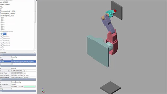
第一个选项是选择电池块的正确变型。在这里,您可以注意到通过选择具有较低保真度的变体,您可以轻松获得任务执行时间的10倍。
另一种选择是选择电池单元的较低订单动态。这也有助于显着减少任务执行时间。这种性能的增益来自降低的保真度。
Now, if your model complexity is lower or number of battery cells in series is less than 50, it is quite possible that you don’t have to do any of this optimization to achieve task execution time of less than 1 millisecond.
正如我们之前讨论的那样,对BMS应用的HIL测试的第二个重要方面是模拟传感器信号和传感器故障。
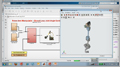
For emulating cell voltages, Speedgoat provides a Battery Emulator Card IO991-06. Each Battery Emulator Card provides 6 isolated channels. Each channel can supply up to 7V, which allows us to simulate different cell chemistries. Additionally, each channel can source up to 300 mA and sink up to 100 mA. Also, Multiple I/O modules can be combined in series or parallel to achieve the required power levels.
In addition to battery voltage emulation, we need Temperature Sensor simulation cards and Fault Insertion cards to complete BMS HIL setup. Speedgoat provides various options for temperature sensor emulator card and fault insertion.
In our demonstration, we have only used IO991 for battery voltage emulation.
Now, let’s see a live demonstration of BMS HIL testing.
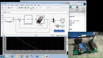
我们从测试模型开始,这使我们能够模拟电池单元并生成故障方案。
在此测试模型中,我们有一个小电池组,其中6个单元串联连接。为了模拟故障,我们添加了一个开关,它允许我们短两个单元终端,而没有任何真实的物理后果并测试控制器的响应。我们使用切换开关块以交互方式注入故障。
受控电流源块用于在滑块块的帮助下模拟充电或放电电流。要在单元格上执行诊断,我们测量两个单元终端之间的电压。
The measured cell voltage values are fed into IO991 Block, which converts these numerical values into electrically isolated voltages each relating to individual battery cell.
The output terminals of IO991-06 card are connected to an electronics board you see in the background here, which makes physical measurements of cell voltages and communicates the information to a BMS controller, which in this case is a Texas Instruments controller board.
The BMS controller performs diagnostics on cell voltages and generate a fault status in the case of over- or undervoltage fault or short between two terminals. In this case, BMS controller turns on the LED in the event of any fault and outputs its status on a digital output port.
We read fault status from BMS controller using Digital Input port of IO133 to check if controller logic is performing as per the requirements.
Now, let’s go ahead and connect to target machine.
Up on executing this model in real time, we can change the current all the way to 10 amperes to check for any overvoltage fault or -10 ampere to check for any undervoltage fault from the controller.
We don’t see any fault yet. When we inject a short-circuit fault, we can immediately notice LED glowing on the controller board and also see our Lamp in the model changing the color from green to red, indicating there is a fault on the controller.
Let’s look at the results in Simulation Data Inspector for whole experiment. We can notice small changes in cell voltages due to change in current. And one of the cell voltages dropped significantly as we triggered the fault, and see the corresponding change in the fault status.
在本演示文稿中,我们演示了如何快速设计和测试BMS算法的大型系统级模型,以及电气,软件等不同域的工程师可以使用Simulink作为公共设计平台进行协作。金宝app我们还讨论了不同的方法,实时运行大电池型号,以进行硬件环路测试。最后,我们展示了如何为BMS应用程序设置HIL测试以及如何帮助您对电池管理系统的设计带来更多的信心。
Product Focus
其他资源
Related Videos and Webinars


选择一个网站
Choose a web site to get translated content where available and see local events and offers. Based on your location, we recommend that you select:.
Select网站您还可以从以下列表中选择一个网站:
美洲
- América Latina(Español)
- 加拿大(英语)
- 美国(英语)