Airframe Trim and Linearize with Simulink® Control Design™
This example shows how to trim and linearize an airframe using Simulink® Control Design™ software
Designing an autopilot with classical design techniques requires linear models of the airframe pitch dynamics for several trimmed flight conditions. The MATLAB® technical computing environment can determine the trim conditions and derive linear state-space models directly from the nonlinear Simulink® and Aerospace Blockset™ model. This step saves time and helps to validate the model. The Simulink Control Design functions allow you to visualize the motion of the airframe in terms of open-loop frequency or time responses.
Initialize Guidance Model
The first problem is to find the elevator deflection, and the resulting trimmed body rate (q), which will generate a given incidence value when the missile is traveling at a set speed. Once the trim condition is found, a linear model can be derived for the dynamics of the perturbations in the states around the trim condition.
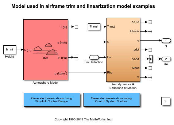
open_system('aeroblk_guidance_airframe');
Define State Values
h_ini = 10000/m2ft;% Trim Height [m]M_ini = 3;% Trim Mach Numberalpha_ini = -10*d2r;% Trim Incidence [rad]theta_ini = 0*d2r;% Trim Flightpath Angle [rad]v_ini = M_ini*(340+(295-340)*h_ini/11000);% Total Velocity [m/s]q_ini = 0;% Initial pitch Body Rate [rad/sec]
Set Operating Point and State Specifications
The first state specifications are Position states. The second state specification is Theta. Both are known, but not at steady state. The third state specifications are body axis angular rates, of which the variable w is at steady state.
opspec = operspec('aeroblk_guidance_airframe'); opspec.States(1).Known = [1;1]; opspec.States(1).SteadyState = [0;0]; opspec.States(2).Known = 1; opspec.States(2).SteadyState = 0; opspec.States(3).Known = [1 1]; opspec.States(3).SteadyState = [0 1];
Search for Operating Point, Set I/O, Then Linearize
op = findop('aeroblk_guidance_airframe',opspec); io(1) = linio('aeroblk_guidance_airframe/Fin Deflection',1,“输入”); io(2) = linio('aeroblk_guidance_airframe/Selector',1,'output'); io(3) = linio(sprintf(['aeroblk_guidance_airframe/Aerodynamics &\n',...'Equations of Motion']),3,'output'); sys = linearize('aeroblk_guidance_airframe',op,io);
操作点搜索报告 : --------------------------------- opreport = Operating point search report for the Model aeroblk_guidance_airframe. (Time-Varying Components Evaluated at time t=0) Operating point specifications were successfully met. States: ---------- Min x Max dxMin dx dxMax _______ ________ _______ _____ __________ _____ (1.) aeroblk_guidance_airframe/Aerodynamics & Equations of Motion/3DOF (Body Axes)/Position 0 0 0 -Inf 967.66 Inf -3048 -3048 -3048 -Inf -170.63 Inf (2.) aeroblk_guidance_airframe/Aerodynamics & Equations of Motion/3DOF (Body Axes)/Theta 0 0 0 -Inf -0.21604 Inf (3.) aeroblk_guidance_airframe/Aerodynamics & Equations of Motion/3DOF (Body Axes)/U,w 967.66 967.66 967.66 -Inf -14.098 Inf -170.63 -170.63 -170.63 0 -7.439e-08 0 (4.) aeroblk_guidance_airframe/Aerodynamics & Equations of Motion/3DOF (Body Axes)/q -Inf -0.21604 Inf 0 3.3582e-08 0 Inputs: ---------- Min u Max ____ _______ ___ (1.) aeroblk_guidance_airframe/Fin Deflection -Inf 0.13615 Inf Outputs: ---------- Min y Max ____ __________ ___ (1.) aeroblk_guidance_airframe/q -Inf -0.21604 Inf (2.) aeroblk_guidance_airframe/az -Inf -7.439e-08 Inf
Select Trimmed States, Create LTI Object, and Plot Bode Response
% find index of desired states in the state vectornames = sys.StateName; q_idx = find(strcmp('q',names)); az_idx = find(strcmp('U,w(2)',names)); airframe = ss(sys.A([az_idx q_idx],[az_idx q_idx]),sys.B([az_idx q_idx],:),sys.C(:,[az_idx q_idx]),sys.D); set(airframe,'inputname',{'Elevator'},...'outputname',[{'az'} {'q'}]); ltiview('bode',airframe);

You can also select a web site from the following list:
Americas
- América Latina(Español)
- Canada(English)
- United States(English)
Europe
- Belgium(English)
- Denmark(English)
- Deutschland(Deutsch)
- España(Español)
- Finland(English)
- France(Français)
- Ireland(English)
- Italia(Italiano)
- Luxembourg(English)
- Netherlands(English)
- Norway(English)
- Österreich(Deutsch)
- Portugal(English)
- Sweden(English)
- Switzerland
- United Kingdom(English)