azel2phithetapat
将辐射模式从方位和高度coordinates to phi-theta coordinates
Syntax
Description
pat_phitheta= azel2phithetapat(pat_azel,az,el)pat_azel, from azimuth and elevation coordinates to the pattern,pat_phitheta, in phi and theta coordinates.azandelare the azimuth and elevation angles at which thepat_azelvalues are defined. Thepat_phithetamatrix covers theta values from 0 to 180 degrees and phi values from 0 to 360 degrees in one degree increments. The function interpolates thepat_azelmatrix to estimate the response of the antenna in a given phi-theta direction.
pat_phitheta= azel2phithetapat(___,'RotateZ2X',rotpatax)rotpataxto indicate the boresight direction of the pattern along thex-axis or thez-axis.
[also returns vectorspat_phitheta,phi_pat,theta_pat] = azel2phithetapat(___)phi_patandtheta_patcontaining the phi and theta angles at whichpat_phithetais sampled.
Examples
Convert Radiation Pattern to Phi-Theta
Convert a radiation pattern to φ/θ form, with the φ and θ angles spaced 1 degree apart.
Define the pattern in terms of azimuth and elevation.
az = -180:180; el = -90:90; pat_azel = mag2db(repmat(cosd(el)',1,numel(az)));
Convert the pattern to φ/θ space.
pat_phitheta = azel2phithetapat(pat_azel,az,el);
Plot Converted Radiation Pattern
Plot the result of converting a radiation pattern to space with the and angles spaced 1 degree apart.
The radiation pattern is the cosine of the elevation.
az = -180:180; el = -90:90; pat_azel = repmat(cosd(el)',1,numel(az));
Convert the pattern to space. Use the returned and angles for plotting.
[pat_phitheta,phi,theta] = azel2phithetapat(pat_azel,az,el);
Plot the result.
H = surf(phi,theta,mag2db(pat_phitheta)); H.LineStyle ='none'; xlabel('phi (degrees)'); ylabel('theta (degrees)'); zlabel('Pattern');

Convert Radiation Pattern to Alternate Phi-Theta Coordinates
Convert a radiation pattern to the alternate phi-theta coordinates, with the phi and theta angles spaced one degree apart.
Create a simple radiation pattern in terms of azimuth and elevation. Add an offset to the pattern to suppress taking the logarithm of zero inmag2db.
az = -180:180; el = -90:90; pat_azel = mag2db(cosd(el).^2'*sind(az).^2 + 1); imagesc(az,el,pat_azel) xlabel('Azimuth (deg)') ylabel('Elevation (deg)') colorbar

Convert the pattern to phi-theta space.
[pat_phitheta,phi_pat,theta_pat] = azel2phithetapat(pat_azel,az,el,'RotateZ2X',false); imagesc(phi_pat,theta_pat,pat_phitheta) xlabel('Phi (deg)') ylabel('Theta (deg)') colorbar

Convert Radiation Pattern for Specific Phi/Theta Values
Convert a radiation pattern to space with and angles spaced 5 degrees apart.
The radiation pattern is the cosine of the elevation.
az = -180:180; el = -90:90; pat_azel = repmat(cosd(el)',1,numel(az));
Define the set of and angles at which to sample the pattern. Then, convert the pattern.
phi = 0:5:360; theta = 0:5:180; pat_phitheta = azel2phithetapat(pat_azel,az,el,phi,theta);
Plot the result.
H = surf(phi,theta,mag2db(pat_phitheta)); H.LineStyle ='none'; xlabel('phi (degrees)'); ylabel('theta (degrees)'); zlabel('Pattern');

Input Arguments
Output Arguments
More About
Azimuth and Elevation Angles
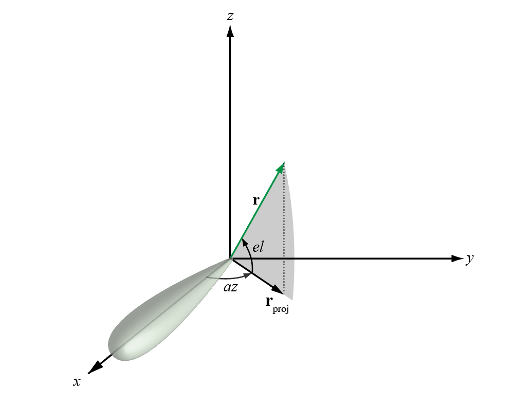
Theazimuth angleof a vector is the angle between thex-axis and the orthogonal projection of the vector onto thexyplane. The angle is positive in going from thexaxis toward theyaxis. Azimuth angles lie between –180 and 180 degrees. Theelevation angleis the angle between the vector and its orthogonal projection onto thexy-plane. The angle is positive when going toward the positivez-axis from thexyplane. By default, the boresight direction of an element or array is aligned with the positivex-axis. The boresight direction is the direction of the main lobe of an element or array.
Note
The elevation angle is sometimes defined in the literature as the angle a vector makes with the positivez-axis. The MATLAB®and Phased Array System Toolbox™ products do not use this definition.
This figure illustrates the azimuth angle and elevation angle for a vector shown as a green solid line.
Phi and Theta Angles
The phi angle (φ) is the angle from the positivey-axis to the vector’s orthogonal projection onto theyzplane. The angle is positive toward the positivez-axis. The phi angle is between 0 and 360 degrees. The theta angle (θ) is the angle from thex-axis to the vector itself. The angle is positive toward theyzplane. The theta angle is between 0 and 180 degrees.
这个数字说明了一个向量φ和θthat appears as a green solid line.

The coordinate transformations between φ/θ andaz/elare described by the following equations
Alternative Definition of Phi and Theta
The phi angle (φ) is the angle from the positivex-axis to the vector’s orthogonal projection onto thexyplane. The angle is positive toward the positivey-axis. The phi angle is between 0 and 360 degrees. The theta angle (θ) is the angle from thez-axis to the vector itself. The angle is positive toward thexyplane. The theta angle is between 0 and 180 degrees.
The figure illustratesφandθfor a vector that appears as a green solid line.

Extended Capabilities
Version History
You can also select a web site from the following list:
Americas
- América Latina(Español)
- Canada(English)
- United States(English)
Europe
- Belgium(English)
- Denmark(English)
- Deutschland(Deutsch)
- España(Español)
- Finland(English)
- France(Français)
- Ireland(English)
- Italia(Italiano)
- Luxembourg(English)
- Netherlands(English)
- Norway(English)
- Österreich(Deutsch)
- Portugal(English)
- Sweden(English)
- Switzerland
- United Kingdom(English)