仿真过程中的在线频率响应估计
此示例演示如何在Simulink®中模拟模型时使用频率响应估计器块执行在线频率响应估计。当您计划部署块以在线估计物理设备时,此方法非常有用。在部署之前,根据工厂的Simulink模型测试估算算法和实验参数,可以帮助确保在线估算对您的工厂是安全的。金宝app
Control System Model
此示例使用已包含配置用于估计的频率响应估计器块的模型。打开模型。
mdl公司=“哦nlinefrequerespestimex.slx文件"; open_system(mdl)
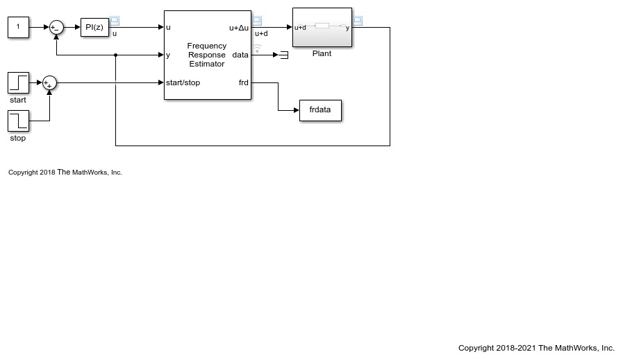
在一个闭环配置模型包含一个工厂u型ration with a PI controller. The Frequency Response Estimator block accepts the control signal as the inputu型.It feeds the control signal plus a perturbation into the plant input. You specify properties of the perturbation signal using parameters of the block.
Experiment Parameters
频率响应估计器模块被配置成在正弦流模式下运行实验,这意味着它在每个频率处注入单独的扰动。该块还被配置为对扰动信号中的每个频率使用相同的振幅1。
所述块进一步配置为估计所述频率处的频率响应w型= logspace(0,2,20).To ensure that the experiment sampling rate is fast enough to accommodate the highest frequency, it is a good practice to set the sampling time to about 0.6 /w型max或者更快,哪里w型maxis the highest frequency in rad/s. For this example, the experiment sample time is 0.005 seconds, is fast enough for thew型max100 rad/s。
启动/停止信号
梯级块连接到启动/停止输入端口打开实验,在t型=5,当模型处于稳态时。该块提供了约174 s的建议实验长度。该值基于指定的频率w型, the number of settling periods to wait at each frequency, and the number of periods to use for estimation. To ensure that the experiment runs long enough for a good result, the启动/停止信号停止实验t型= 180. (有关建议的实验长度的详细信息,请参阅频率响应估计器.)
估算结果
模拟模型。您可以使用示波器来可视化控制信号、扰动信号和设备输出。因为Display Bode Plot如果选择块参数,块将自动生成指定基线模型的图,并使用估计的频率响应定期更新该图。
sim卡(mdl)

The signal at thefrd公司端口是一个向量,包含在每个频率下的估计响应的当前值w型.The To Workspace block connected to that port writes the signal to the MATLAB® workspace variablefrdata公司.In the To Workspace block, the将数据点限制为最后一个参数设置为1,以便frdata公司仅包含每个频率下的最终估计响应。转换frdata公司t型o afrd公司模型对象。
sys\u estim=frd(frdata,w);大小(sys\u estim)
具有1个输出、1个输入和20个频点的FRD模型。
您现在可以使用系统估计带控制系统工具箱™ 接受的分析和控制设计命令frd公司模型作为输入,例如bodeandpidtune. 或者,如果您有系统标识工具箱™ 软件中,您可以使用频率响应数据来估计系统的参数化模型。
记录的实验数据
该模型还配置为在块输出端口数据处记录估计数据(参见使用信号记录导出信号数据for information about data logging). The data is stored in the MATLAB workspace as the金宝appSimulink.SimulationData.Dataset数据集对象罗格苏特. 有关如何使用此数据的信息,请参阅采集频率响应实验数据进行离线估计.
另请参见
Related Topics
You can also select a web site from the following list:
美洲
- América Latina(Español)
- 加拿大(英文)
- 美国(英文)