从投影数据重建图像
This example shows how to useradon,iradon,fanbeam,和ifanbeam从采样图像形成投影,然后从投影中重建图像。而radon和iradonuse a parallel-beam geometry for the projections,fanbeam和ifanbeamuse a fan-beam geometry. To compare parallel-beam and fan-beam geometries, the examples below create synthetic projections for each geometry and then use those synthetic projections to reconstruct the original image.
需要图像重建的实际应用是X射线吸收层面,其中通过测量通过不同角度通过物理样品的辐射的衰减来形成突起。原始图像可以被认为是通过标本作为横截面,其中强度值表示样本的密度。通过特殊的医学成像装置收集投影,然后使用样本的内部图像进行重建iradon要么ifanbeam。
功能iradon从并行束投影重建图像。在并行束几何形状中,通过以特定角度组合通过图像的一组积分来形成每个突起。功能ifanbeamreconstructs an image from fan-beam projections, which have one emitter and multiple sensors.
有关说明几何图形的图表,请参阅图像处理工具箱™用户指南。
创造头部幻影
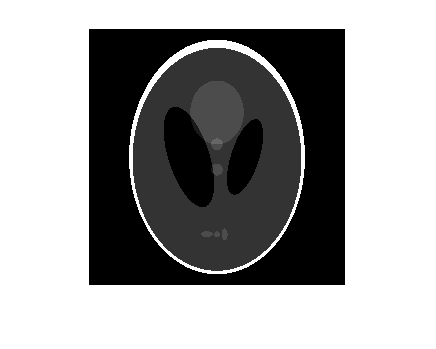
The test image is the Shepp-Logan head phantom which can be generated using the functionphantom。幻影图像说明了在人类头部的真实层析成像中发现的许多品质。沿外外部的明亮椭圆形壳类似于颅骨,而且许多椭圆内部类似于脑特征或肿瘤。
p = phantom(256);imshow(p)
平行光束 - 计算合成投影
使用平行束几何计算合成突起,并改变投影角度的数量。对于每个来电来说radon, the output is a matrix in which each column is the Radon transform for one of the angles in the correspondingtheta。
theta1 = 0:10:170; [R1,~] = radon(P,theta1); num_angles_R1 = size(R1,2)
num_angles_r1 = 18.
Theta2 = 0:5:175;[r2,〜] =氡(p,theta2);num_angles_r2 = size(r2,2)
num_angles_R2 = 36
THETA3 = 0:2:178;[R3,XP] =氡(P,THETA3);num_angles_r3 = size(r3,2)
num_angles_R3 = 90
Note that for each angle, the projection is computed atN沿XP轴点点,在哪里N是取决于图像的对角线距离的常数,使得每个像素将被投射所有可能的投影角度。
n_r1 = size(r1,1)
N_R1 = 367
n_r2 = size(r2,1)
N_R2 = 367
n_r3 = size(r3,1)
N_R3 = 367
So, if you use a smaller head phantom, the projection needs to be computed at fewer points along the xp-axis.
p_128 =幻影(128);[r_128,xp_128] =氡(p_128,theta1);n_128 = size(r_128,1)
N_128 = 185
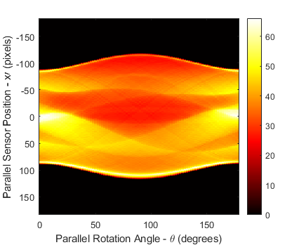
显示投影数据R3。原始幻像图像的一些特征在图像中可见R3。第一列R3corresponds to a projection at 0 degrees, which is integrating in the vertical direction. The centermost column corresponds to a projection at 90 degrees, which is integrating in the horizontal directions. The projection at 90 degrees has a wider profile than the projection at 0 degrees due to the large vertical semi-axis of the outermost ellipse of the phantom.
imagesc(theta3,xp,R3) colormap(hot) colorbar xlabel('Parallel Rotation Angle - \theta (degrees)');ylabel('并行传感器位置 - X \ Prime(像素)');
平行光束 - 从投影数据重建头部幻像
匹配并行旋转增量,Dtheta., in each reconstruction with that used above to create the corresponding synthetic projections. In a real-world case, you would know the geometry of your transmitters and sensors, but not the source image,P。
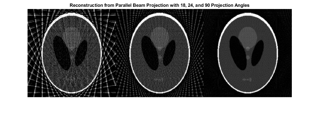
The following three reconstructions (I1,I2,和I3)显示改变制造突起的角度的效果。对于I1和I2some features that were visible in the original phantom are not clear. Specifically, look at the three ellipses at the bottom of each image. The result inI3closely resembles the original image,P。
请注意,重要的伪影I1和I2。To avoid these artifacts, use a larger number of angles.
%约束每个重建的输出大小与% size of the original image, |P|.output_size = max(size(P)); dtheta1 = theta1(2) - theta1(1); I1 = iradon(R1,dtheta1,output_size); dtheta2 = theta2(2) - theta2(1); I2 = iradon(R2,dtheta2,output_size); dtheta3 = theta3(2) - theta3(1); I3 = iradon(R3,dtheta3,output_size); figure montage({I1,I2,I3},'尺寸',[1 3]) title('Reconstruction from Parallel Beam Projection with 18, 24, and 90 Projection Angles')
风扇梁 - 计算合成投影
Calculate synthetic projections using fan-beam geometry and vary the 'FanSensorSpacing'.
D = 250; dsensor1 = 2; F1 = fanbeam(P,D,'fansensorspacing',dsensor1);dsensor2 = 1;f2 = fanbeam(p,d,'fansensorspacing',dsensor2); dsensor3 = 0.25; [F3, sensor_pos3, fan_rot_angles3] = fanbeam(P,D,。。。'fansensorspacing',dsensor3);
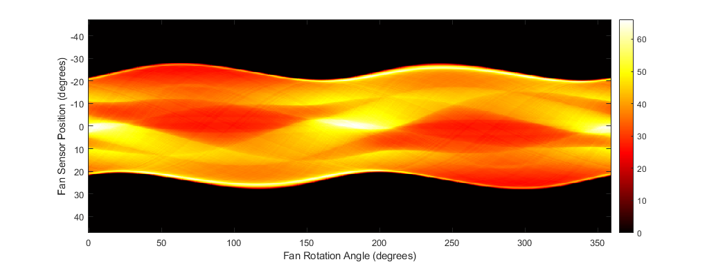
显示投影数据F3。Notice that the fan rotation angles range from 0 to 360 degrees and the same patterns occur at an offset of 180 degrees because the same features are being sampled from both sides. You can correlate features in this image of fan-beam projections with the same features in the image of parallel-beam projections, above.
ImagesC(FAN_ROT_ANGLES3,SENSOR_POS3,F3)COLOROMAP(HOT)COLORBAR XLABEL('风扇旋转角度(度)')ylabel('风扇传感器位置(度)')
Fan Beam - Reconstruct Head Phantom from Projection Data
将每次重建中的扇形传感器间距匹配,用于创建每个合成投影。在一个真实的情况下,您会知道发射器和传感器的几何形状,但不是源图像,P。
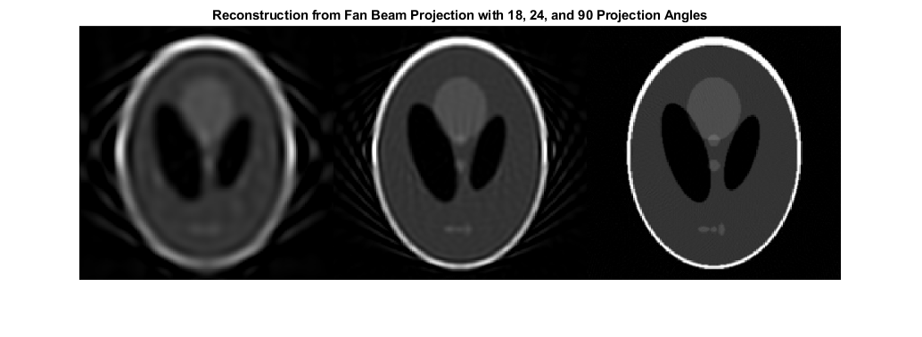
改变“粉丝段间隔”的值有效地改变了每个旋转角度使用的传感器的数量。对于这些扇形重建中的每一个,使用相同的旋转角度。这与每个使用不同的旋转角度的平行光束重建相反。
Note that 'FanSensorSpacing' is only one parameter of several that you can control when usingfanbeam和ifanbeam。您还可以使用功能来回转换并行和扇形光束投影数据之间fan2para和para2fan。
Ifan1 = ifanbeam(F1,D,'fansensorspacing',dsensor1,'OutputSize',output_size);Ifan2 = ifanbeam(F2,D,'fansensorspacing',dsensor2,'OutputSize',output_size);Ifan3 = ifanbeam(F3,D,'fansensorspacing',dsensor3,'OutputSize',output_size);图蒙太奇({ifan1,ifan2,ifan3},'尺寸',[1 3]) title('从粉丝梁投射重建,18,24和90投影角度')
选择一个网站
Choose a web site to get translated content where available and see local events and offers. Based on your location, we recommend that you select:。
Select网站您还可以从以下列表中选择一个网站: