在上一个视频中,我们建模了一个三相逆变器,该逆变器将直流功率转换为三相电流以控制BLDC电机。三相逆变器的输入是一种开关模式,可控制电动机相对的开关状态和关闭状态。在上一个视频中,我们使用静态开关模式为阶段A和C供电,并观察到转子在30度处与定子磁场对齐。在此视频中,我们将在此模型中添加换向逻辑,以动态更改转子连续旋转的开关模式。
As we discussed in our second Tech Talk video, we need a Hall effect sensor to determine which sector the rotor is in. Commutation logic then uses the current sector to select the corresponding switching pattern. Let’s start with modeling the Hall effect sensor. In practice, Hall effect sensors sense the magnetic field around each phase to determine the current sector. For simulation purposes, however, we’ll assume that we know the angular rotor position from which we’ll compute the sectors. The logic for the Hall effect sensor model should be the following: If the rotor is between 0 and 60 degrees, then it means the rotor is in the first sector, so we should output 1. Similarly, there are five more cases until we complete the full rotation of the rotor.
让我们在此处保留此表,并尝试在Simulink中建模相同的逻辑。金宝app角位置theta始终在0到360度之间,这意味着在转子的每次旋转后,我们都应将theta重置为0度。我们可以使用数学功能块中可用的剩余函数来做到这一点。我们将将theta输入到该块360的恒定值,然后将其剩余的从theta的划分返回360度。我们还将在此处插入一个增益块,并输入杆对P的数量,即在我们的情况下为1,并且已经在MATLAB工作区中定义了。这样,我们代表电气度的转子位置。现在,我们准备好使用此逻辑。
对于每种情况,我们需要检查两个条件。为了实现第一个检查,我们添加了一个常数块,我们将其设置为0。然后我们抓住一个关系操作员块,然后选择要使用的正确操作员与0进行比较。类似地,我们对第二个条件进行建模。当满足这两个条件时,我们希望将扇区设置为1。我们可以使用AN和GATE以及代表扇形号码的增益来做到这一点。请注意,逻辑运算符会输出一个布尔值,我们需要将其转换为与增益相同的数据类型。我们可以使用数据类型转换块来做到这一点,该块将布尔值转换为从增益块中继承的数据类型。
根据该逻辑,当满足两个条件时,运算符和操作员将返回1,并且将扇区设置为1。如果未满足任何一个或两个条件,则输出为0,因为这将意味着转子在另一个部门。
为了实现其余条件,我们可以简单地复制和粘贴此部分,然后像图片中一样调整值。现在,结果值的总和将为我们提供扇区号。请注意,每次只有这些输出中的一个将为正,其余的将为0。让我们选择此部分并创建一个我们将调用传感器的子系统。
现在,我们已经完成了计算该扇区的完成,我们可以使用它来对换向逻辑进行建模。正如我们在第二个技术谈话视频中讨论的那样,换向逻辑基本上就像一张包含所有可能的切换模式的表,并以正确的顺序输出它们,以根据扇区信息正确旋转转子。
Here we have the first switching pattern. Let’s disconnect this and add the remaining switching patterns that we see in the picture. In order to choose a pattern based on the sector, we’re going to use a switch. We use the Multiport Switch block for this. We need six inputs, which we connect to the switching patterns we just created. The first input is controlling this switch by telling it what pattern to choose, so here we need to connect the sector. Let’s select all of this and create a subsystem which we can call “Commutation Logic”. With that we closed a loop around the motor, which lets us energize the correct phases for continuous rotation based on the sector that we determine by using Hall effect sensors.
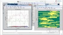
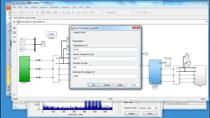
现在,我们将记录开关模式以及“ Theta”。我们将使用上一个视频中的相同脚本,该视频使用已记录的信号来对仿真结果进行动画。我们首先运行模拟,然后通过在命令行中键入其名称来调用我们的脚本。我们看到一切都按预期工作。这意味着我们正在正确计算该扇区,并基于换向逻辑选择正确的切换模式。现在,我们正在控制电动机,但只有在这里看到的,只有持续的速度。因为电源电压是恒定的。为了能够以不同的速度运行电动机,我们需要一个反馈控制器,将电源电压调整为三相逆变器。为了构建此控制循环,我们首先需要计算所需速度和测量速度之间的误差,然后将其输入控制器以调节电压水平。我们测量传感器块下的速度。 Let’s first output the measured speed with an Outport block. We will compare it to a desired speed which we can model using a repeating sequence changing gradually from 0 to 900 RPMs. We insert a Sum block to compute the error between desired and measured speeds which we then input into a PID controller. For speed control, we choose to use a discrete PI-controller. As I tuned the gains before and already know what values work well for my system, I’ll just enter them here. Next, we add a unit delay to prevent any algebraic loop that may occur in this model. Now, we need to feed the voltage computed by the controller into the three-phase inverter. So, we remove the current voltage source and replace it with an ideal voltage source which provides the commanded voltage regardless of the current passing through it.
接下来,我们将记录不同的信号,以便在模拟系统后能够查看它们。现在,我们可以运行模型,并查看所需和测量的速度以及控制器计算的电压。我们看到三相逆变器的电压受控制器的调节,测量速度成功跟踪所需的速度。注意电压和电动机速度如何按比例变化。
总而言之,在此视频中,我们向您展示了如何对换向逻辑进行建模,并通过反馈控制器控制电动机速度。在此模型中,我们使用理想的电压来源调节电压水平。但实际上,电源电压是固定的,我们需要使用称为PWM或脉冲宽度调制的技术对其进行调整。下次,我们将讨论PWM和用于实现PWM控制的不同体系结构。