Bode Diagram Design
Bode diagram design is an interactive graphical method of modifying a compensator to achieve a specific open-loop response (loop shaping). To interactively shape the open-loop response using控制系统设计师, use theBODE编辑器。在里面editor, you can adjust the open-loop bandwidth and design to gain and phase margin specifications.
要调整循环形状,您可以在补偿器中添加杆和零并直接调整它们的值BODE编辑器,或者您可以使用补偿器编辑器。有关更多信息,请参阅编辑补偿器动力学。
有关可用的所有调整方法的信息控制系统设计师, see控制系统设计器调整方法。
Tune Compensator For DC Motor Using Bode Diagram Graphical Tuning
This example shows how to design a compensator for a DC motor using Bode diagram graphical tuning techniques.
Plant Model and Requirements
如下所述的DC电机设备的传递功能Siso示例:直流电机, is:
对于此示例,设计要求是:
Rise time of less than 0.5 seconds
稳态误差小于5%
Overshoot of less than 10%
Gain margin greater than 20 dB
Phase margin greater than 40 degrees
开放控制系统设计师
在Matlab.®命令行,创建工厂的传输功能模型,打开控制系统设计师in the Bode Editor configuration.
g = tf(1.5,[14 40.02]);ControlSystemDesigner('bode',G);
The app opens and importsGas the plant model for the default control architecture,配置1。
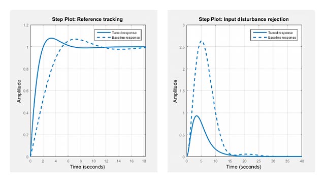
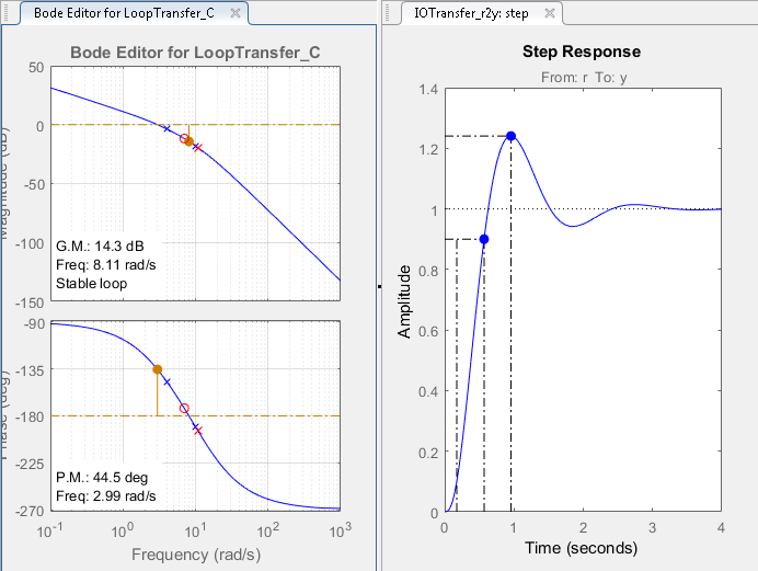
在里面app, the following response plots open:
Open-loopBODE编辑器为了
LoopTransfer_C响应。This response is the open-loop transfer functionGC,在哪里Cis the compensator andGis the plant.Step Response为了
IOTransfer_r2y响应。此响应是整个闭环系统的输入输出传输功能。
Tip
To open the open-loopBODE编辑器when控制系统设计师is already open, on theControl System标签,在调整方法drop-down list, selectBODE编辑器。在里面Select Response to Edit dialog box, select an existing response to plot, or create a新的开环响应。
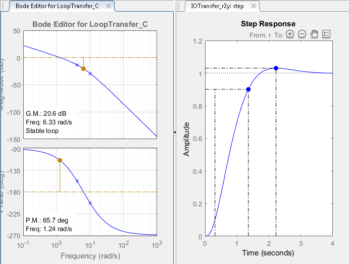
To view the open-loop frequency response and closed-loop step response simultaneously, on theViewstab, click左右。

该应用程序显示BODE编辑器和Step Responseplots side-by-side.
Adjust Bandwidth
Since the design requires a rise time less than 0.5 seconds, set the open-loop DC crossover frequency to about 3 rad/s. To a first-order approximation, this crossover frequency corresponds to a time constant of 0.33 seconds.
要使交叉更容易看到,请打开绘图网格。右键单击BODE编辑器plot area, and select格。该应用程序将网格添加到Bode响应图中。
调整交叉频率增加补偿器增益。在里面BODE编辑器plot, in theMagnituderesponse plot, drag the response upward. Doing so increases the gain of the compensator.
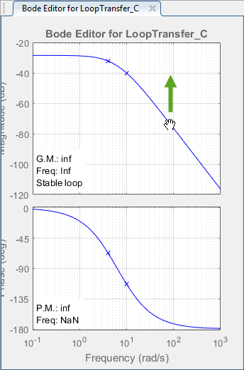
As you drag the magnitude plot, the app computes the compensator gain and updates the response plots.
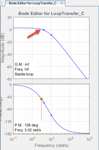
向上拖动幅度响应,直到交叉频率约为3 rad / s。
View Step Response Characteristics
To add the rise time to theStep Responseplot, right-click the plot area, and select特点>上升时间。
To view the rise time, move the cursor over the rise time indicator.
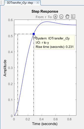
The rise time is around 0.23 seconds, which satisfies the design requirements.
同样,将峰值响应添加到Step Responseplot, right-click the plot area, and select特点>峰值响应。
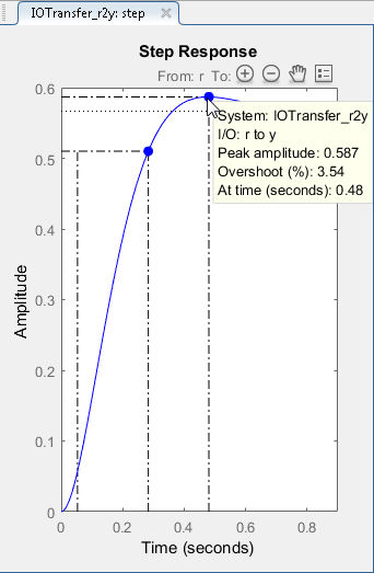
The peak overshoot is around 3.5%.
Add Integrator To Compensator
To meet the 5% steady-state error requirement, eliminate steady-state error from the closed-loop step response by adding an integrator to your compensator. In theBODE编辑器right-click in the plot area, and selectAdd Pole/Zero>积分商。
添加集成器产生零稳态误差。但是,改变补偿器动力学也会改变交叉频率,增加上升时间。为了减少上升时间,将交叉频率增加到大约3 rad / s。
调整补偿器增益
要将交叉频率返回到左右3 rad / s,请进一步增加补偿器增益。右键单击BODE编辑器plot area, and select编辑补偿器。
在“补偿器编辑器”对话框中,在赔偿者section, specify a gain of99.,并按Enter。
The response plots update automatically.
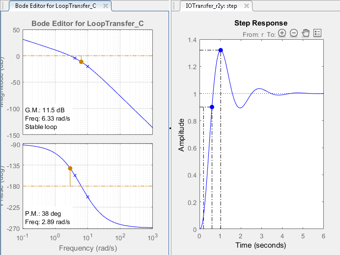
上升时间约为0.4秒,满足设计要求。但是,峰值过冲约占32%。由增益和积分器组成的补偿器不足以满足设计要求。因此,补偿器需要额外的动态。
将铅网添加到补偿器
在里面BODE编辑器,回顾当前补偿器设计的增益裕度和相位余量。该设计需要大于20 dB的增益边缘,相距大于40度。目前的设计不符合这些要求中的任何一种。
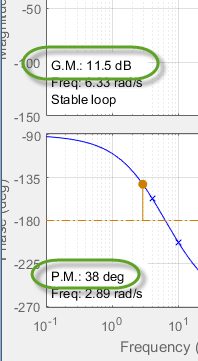
为了增加稳定性边距,将铅网添加到补偿器。
在里面BODE编辑器,右键单击并选择Add Pole/Zero>铅。
To specify the location of the lead network pole, click on the magnitude response. The app adds a real pole (redX)和真实零(红色O) to the compensator and to theBODE编辑器情节。
在里面BODE编辑器,拖动杆和零来更改其位置。拖动它们时,应用程序更新杆/零值并更新响应绘图。
To decrease the magnitude of a pole or zero, drag it towards the left. Since the pole and zero are on the negative real axis, dragging them to the left moves them closer to the origin in the complex plane.
Tip
拖动杆或零时,应用程序在右侧显示状态栏中的新值。
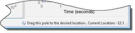
作为初始估计,将零拖动到周围的位置-7和the pole to a location around-11。
The phase margin meets the design requirements; however, the gain margin is still too low.
编辑引线网络杆和零
To improve the controller performance, tune the lead network parameters.
在“补偿器编辑器”对话框中,在动力学部分,单击铅行。
在里面Edit Selected Dynamicssection, in theReal Zero文本框,指定位置-4.3.,并按Enter。该值靠近直流电机设备的最慢(最左侧)杆。
在里面真杆子text box, specify a value of-28,并按Enter。

当您修改引线网络参数时,赔偿者和响应图自动更新。
在应用程序中,在BODE编辑器,增益余量20.5just meets the design requirement.
要在系统中添加稳健性,请在“补偿器编辑器”对话框中,减少补偿器增益84.5,并按Enter。增益保证金增加到21.8, and the response plots update.

在控制系统设计师, in the response plots, compare the system performance to the design requirements. The system performance characteristics are:
上升时间为0.445秒。
稳态误差为零。
过冲3.39%。
Gain margin is 21.8 dB.
Phase margin is 65.6 degrees.
The system response meets all of the design requirements.
See Also
相关话题
选择一个网站
Choose a web site to get translated content where available and see local events and offers. Based on your location, we recommend that you select:。
Select网站您还可以从以下列表中选择一个网站: