调整两环自动驾驶仪
此示例显示了如何使用Simulink控制设计来调整两层自动驾金宝app驶仪,以控制机身的音高速率和垂直加速度。
Model of Airframe Autopilot
The airframe dynamics and the autopilot are modeled in Simulink.
open_system('rct_airframe1')
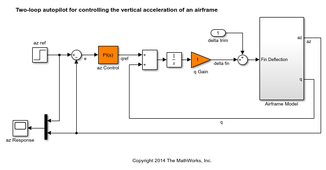
The autopilot consists of two cascaded loops. The inner loop controls the pitch rate q, and the outer loop controls the vertical accelerationaz响应飞行棒命令azref。在此架构中,可调元素包括PI控制器的增益(“ AZ Control”块)和螺距速率增益(“ Q增益”块)。必须调整自动驾驶仪以响应步骤命令azrefin about 1 second with minimal overshoot. In this example, we tune the autopilot gains for one flight condition corresponding to zero incidence and a speed of 984 m/s.
To analyze the airframe dynamics, trim the airframe for and
and 。The trim condition corresponds to zero normal acceleration and pitching moment (
 and
and 稳定的)。采用
findop计算相应的闭环操作condition. Note that we added a "delta trim" input port so thatfindop可以调整翅片偏转to produce the desired equilibrium of forces and moments.
opspec = operspec('rct_airframe1');%指定装饰条件%XE,ZE:已知,不稳定opspec.States(1).Known = [1;1]; opspec.States(1).SteadyState = [0;0];% u,w: known, w steadyopspec.States(3).Known = [1 1]; opspec.States(3).SteadyState = [0 1];% theta: known, not steadyopspec.states(2)。已知= 1;opspec.states(2).steadystate = 0;%问:未知,稳定opspec.states(4)。已知= 0;opspec.States(4).steadystate = 1;% integrator states unknown, not steadyopspec.States(5).SteadyState = 0; opspec.States(6).SteadyState = 0; op = findop('rct_airframe1',opspec);
Operating point search report: --------------------------------- opreport = Operating point search report for the Model rct_airframe1. (Time-Varying Components Evaluated at time t=0) Operating point specifications were successfully met. States: ---------- Min x Max dxMin dx dxMax ___________ ___________ ___________ ___________ ___________ ___________ (1.) rct_airframe1/Airframe Model/Aerodynamics & Equations of Motion/ Equations of Motion (Body Axes)/Position 0 0 0 -Inf 984 Inf -3047.9999 -3047.9999 -3047.9999 -Inf 0 Inf (2.) rct_airframe1/Airframe Model/Aerodynamics & Equations of Motion/ Equations of Motion (Body Axes)/Theta 0 0 0 -Inf -0.0097235 Inf (3.) rct_airframe1/Airframe Model/Aerodynamics & Equations of Motion/ Equations of Motion (Body Axes)/U,w 984 984 984 -Inf 22.6897 Inf 0 0 0 0 -1.4367e-11 0 (4.) rct_airframe1/Airframe Model/Aerodynamics & Equations of Motion/ Equations of Motion (Body Axes)/q -Inf -0.0097235 Inf 0 1.1477e-16 0 (5.) rct_airframe1/Integrator -Inf 0.00070807 Inf -Inf -0.0097235 Inf (6.) rct_airframe1/az Control/Integrator/Continuous/Integrator -Inf 0 Inf -Inf 0.00024207 Inf Inputs: ---------- Min u Max __________ __________ __________ (1.) rct_airframe1/delta trim -Inf 0.00070807 Inf Outputs: None ----------
Linearize the "Airframe Model" block for the computed trim conditionop并绘制鳍挠度的收益delta到azand问:
G = linearize('rct_airframe1','rct_airframe1/机身模型',op); G.InputName ='三角洲';G.OutputName = {'az','q'}; bodemag(G), grid

Note that the airframe model has an unstable pole:
杆(G)
ANS = -0.0320 -0.0255 0.1253 -29.4685
Frequency-Domain Tuning with LOOPTUNE
You can use thelooptune自动调整多环控制系统的功能受基本要求,例如积分动作,足够的稳定性边距和所需的带宽。申请looptune到the autopilot model, create an instance of theslTuner接口并指定simulink块“ AZ控件”和“ Q增益”金宝app为可调。还指定修剪条件op到correctly linearize the airframe dynamics.
ST0 = slTuner('rct_airframe1',{'az Control','Q增益'},op);
将参考,控制和测量信号标记为分析和调整的兴趣点。
addPoint(ST0,{'az ref','delta Fin','az','q'});
最后,调整控制系统参数以满足1秒的响应时间要求。在频域中,这大致对应于增益交叉频率厕所在工厂输入“ Delta Fin”的开环响应中,= 5 rad/s。
wc = 5;控制='delta Fin';测量= {'az','q'}; [ST,gam,Info] = looptune(ST0,Controls,Measurements,wc);
Final: Peak gain = 1.01, Iterations = 69
要求标准化,因此接近1的最终值意味着满足所有要求。通过图形验证设计来确认这一点。
数字('Position',[100,100,560,714]) loopview(ST,Info)
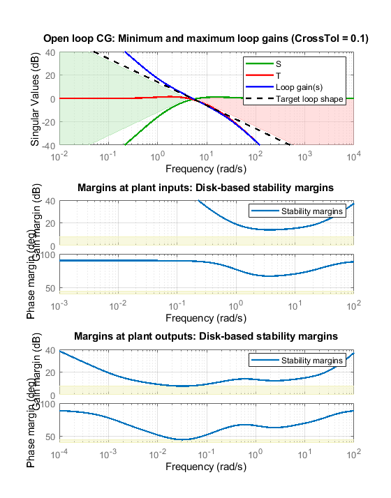
The first plot confirms that the open-loop response has integral action and the desired gain crossover frequency while the second plot shows that the MIMO stability margins are satisfactory (the blue curve should remain below the yellow bound). Next check the response from the step commandazref到垂直加速度az:
t = getiotransfer(st,'az ref','az');figure step(T,5)

The accelerationaz不追踪azrefdespite the presence of an integrator in the loop. This is because the feedback loop acts on the two variablesazand问and we have not specified which one should trackazref。
Adding a Tracking Requirement
要解决这个问题,请添加明确的要求azshould follow the step commandazrefwith a 1 second response time. Also relax the gain crossover requirement to the interval [3,12] to let the tuner find the appropriate gain crossover frequency.
TrackReq = TuningGoal.Tracking('az ref','az',1); ST = looptune(ST0,Controls,Measurements,[3,12],TrackReq);
最终:峰值增益= 1.23,迭代= 54
The step response fromazref到azis now satisfactory:
tr1 = getiotransfer(st,'az ref','az');步骤(TR1,5)网格

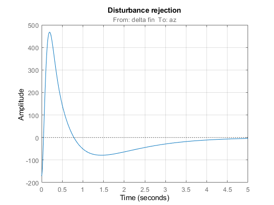
还可以通过查看进入工厂输入的骚乱的响应来检查干扰拒绝特征
td1 = getiotransfer(st,'delta Fin','az');Bodemag(TD1)网格

步骤(TD1,5) grid title('Disturbance rejection')
采用showblockvalue查看PI控制器和内环增益的调谐值
ShowBlockValue(ST)
AnalysisPoints_ = D = u1 u2 u3 u4 y1 1 0 0 0 y2 0 1 0 0 y3 0 0 1 0 y4 0 0 0 1 Name: AnalysisPoints_ Static gain. ----------------------------------- az_Control = 1 Kp + Ki * --- s with Kp = 0.00166, Ki = 0.0017 Name: az_Control Continuous-time PI controller in parallel form. ----------------------------------- q_Gain = D = u1 y1 1.985 Name: q_Gain Static gain.
If this design is satisfactory, use写blockvalue将调谐值应用于Simulink模型,并在Simulink中模拟调谐金宝app控制器。
WriteBlockValue(ST)
MIMO Design with SYSTUNE
Cascaded loops are commonly used for autopilots. Yet one may wonder how a single MIMO controller that uses bothazand问到generate the actuator command三角洲鳍would compare with the two-loop architecture. Trying new control architectures is easy withsystuneorlooptune。对于品种,我们现在使用systune到tune the following MIMO architecture.
open_system('rct_airframe2')

和以前一样,计算修剪条件and。
opspec = operspec('rct_airframe2');%指定装饰条件%XE,ZE:已知,不稳定opspec.States(1).Known = [1;1]; opspec.States(1).SteadyState = [0;0];% u,w: known, w steadyopspec.States(3).Known = [1 1]; opspec.States(3).SteadyState = [0 1];% theta: known, not steadyopspec.states(2)。已知= 1;opspec.states(2).steadystate = 0;%问:未知,稳定opspec.states(4)。已知= 0;opspec.States(4).steadystate = 1;%控制器状态未知,不稳定opspec.States(5).SteadyState = [0;0]; op = findop('rct_airframe2',opspec);
Operating point search report: --------------------------------- opreport = Operating point search report for the Model rct_airframe2. (Time-Varying Components Evaluated at time t=0) Operating point specifications were successfully met. States: ---------- Min x Max dxMin dx dxMax ___________ ___________ ___________ ___________ ___________ ___________ (1.) rct_airframe2/Airframe Model/Aerodynamics & Equations of Motion/ Equations of Motion (Body Axes)/Position 0 0 0 -Inf 984 Inf -3047.9999 -3047.9999 -3047.9999 -Inf 0 Inf (2.) rct_airframe2/Airframe Model/Aerodynamics & Equations of Motion/ Equations of Motion (Body Axes)/Theta 0 0 0 -Inf -0.0097235 Inf (3.) rct_airframe2/Airframe Model/Aerodynamics & Equations of Motion/ Equations of Motion (Body Axes)/U,w 984 984 984 -Inf 22.6897 Inf 0 0 0 0 2.4588e-11 0 (4.) rct_airframe2/Airframe Model/Aerodynamics & Equations of Motion/ Equations of Motion (Body Axes)/q -Inf -0.0097235 Inf 0 -4.0169e-16 0 (5.) rct_airframe2/MIMO Controller -Inf 0.00065361 Inf -Inf -0.0089973 Inf -Inf 2.6167e-19 Inf -Inf 0.030259 Inf Inputs: ---------- Min u Max __________ __________ __________ (1.) rct_airframe2/delta trim -Inf 0.00043574 Inf Outputs: None ----------
As withlooptune, 使用slTunerinterface to configure the Simulink model for tuning. Note that the signals of interest are already marked as Linear Analysis points in the Simulink model.
ST0 = slTuner('rct_airframe2',“ MIMO控制器”,op);
Try a second-order MIMO controller with zero feedthrough frome到三角洲鳍。为此,创建所需的控制器参数化,并将其与“ MIMO控制器”块相关联setBlockParam:
C0 = tunableSS('C',2,1,2);%二阶控制器C0.D.Value(1) = 0;% Fix D(1) to zeroC0.D.Free(1) = false; setBlockParam(ST0,“ MIMO控制器”,C0)
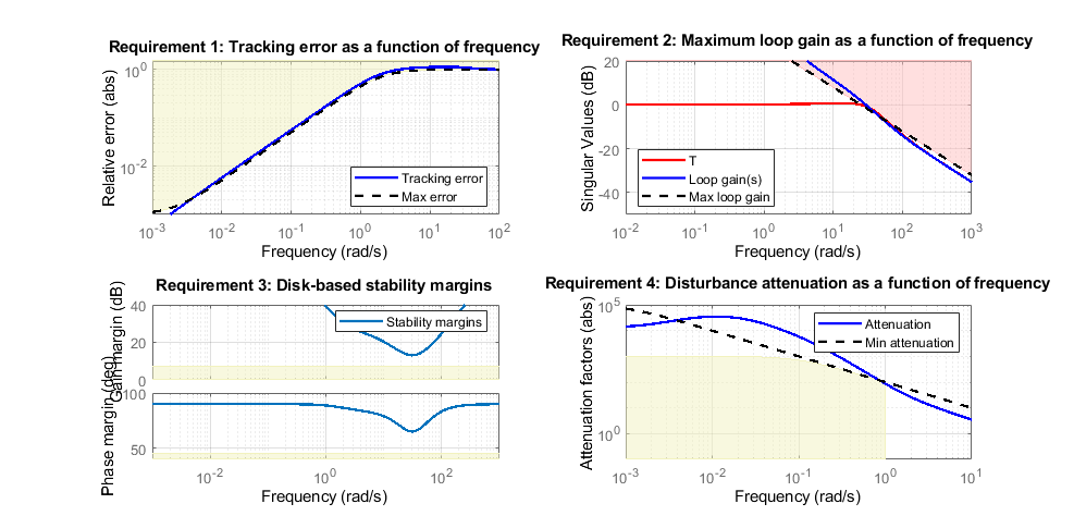
Next create the tuning requirements. Here we use the following four requirements:
Tracking:
azshould respond in about 1 second to theazrefcommandBandwidth and roll-off: The loop gain at
三角洲鳍应在25 rad/s后用-20 dB/十年坡度滚开稳定边缘: The margins at
三角洲鳍should exceed 7 dB and 45 degreesDisturbance rejection: The attenuation factor for input disturbances should be 40 dB at 1 rad/s increasing to 100 dB at 0.001 rad/s.
% 追踪req1 = tuninggoal.tracking('az ref','az',1);% Bandwidth and roll-offReq2 = TuningGoal.MaxLoopGain('delta Fin',tf(25,[1 0]));% Marginsreq3 = tuninggoal.margins('delta Fin',7,45);% Disturbance rejection% Use an FRD model to sketch the desired attenuation profile with a few pointsFreqs = [0 0.001 1]; MinAtt = [100 100 40];DB中的%Req4 = TuningGoal.Rejection('delta Fin',frd(db2mag(MinAtt),Freqs)); Req4.Focus = [0 1];
您现在可以使用systune调整受这些要求的控制器参数。
allreqs = [req1,req2,req3 req4];opt = SystuneOptions(“随机启动”,3);RNG(0)[ST,FSOFT] = Systune(ST0,Allreqs,opt);
最终:soft = 1.42,硬= -inf,迭代= 47 final:soft = 1.42,hard = -inf,迭代= 62 final:soft = 1.14,hard = -inf,迭代,迭代= 86 final = 1.14,soft = 1.14,硬=-inf,迭代= 112
最佳设计的总体目标值接近1,表明几乎满足了所有四个要求。采用viewGoal检查每个要求是否最佳设计。
数字('Position',[100,100,987,474])ViewGoal(Allreqs,ST)
计算闭环响应,并与两环设计进行比较。
t = getiotransfer(st,{'az ref','delta Fin'},'az');图步(tr1,'b',T(1),'r',5) title('Tracking') 传奇('Cascade','2 dof')

步骤(TD1,'b',t(2),'r',5) title('Disturbance rejection') 传奇('Cascade','2 dof')
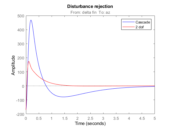
The tracking performance is similar but the second design has better disturbance rejection properties.
也可以看看
looptune(sltuner)(金宝appSimulink控制设计)|slTuner(金宝appSimulink控制设计)
Related Topics
You can also select a web site from the following list:
Americas
- América Latina(Español)
- 加拿大(英语)
- United States(英语)