Induction Machine Direct Torque Control
Induction machine DTC
- 库:
Simscape / Electrical / Control / Induction Machine Control
Description
TheInduction Machine Direct Torque Controlblock implements an induction machine direct torque control (DTC) structure. The figure shows the equivalent circuit for the block.

Equations
To estimate the torque and flux, theInduction Machine Direct Torque Controlblock discretizes the machine voltage equations in the stationaryɑβreference frame using the backward Euler method. The discrete-time equations for stator fluxes in theɑβframe are:
and
where:
vɑisɑ-axis voltage.
iɑisɑ-axis current.
Rsis the stator resistance.
Ψɑis theɑ-axis stator flux.
vβisβ-axis voltage.
iβisβ-axis current.
Ψβis theβ-axis stator flux.
The block calculates the torque and flux as:
and
where:
pis the number of pole pairs.
Ψsis the stator flux.
To detect flux and torque estimation errors, the block uses hysteresis comparators. The figure shows hysteresis comparators and the associated switching sectors.
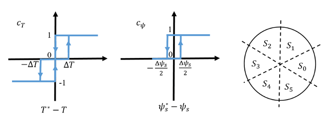
The table shows the optimum switching for an inverter high-side system.
| cΨ,cTS(θ) | S0 | S1 | S2 | S3 | S4 | S5 | |
|---|---|---|---|---|---|---|---|
| cΨ= 1 | cT= 1 | 1, 1, 0 |
0, 1, 0 |
0, 1, 1 |
0, 0, 1 |
1, 0, 1 |
1, 0, 0 |
| cT= 0 | 1, 1, 1 |
0, 0, 0 |
1, 1, 1 |
0, 0, 0 |
1, 1, 1 |
0, 0, 0 |
|
| cT= -1 | 1, 0, 1 |
1, 0, 0 |
1, 1, 0 |
0, 1, 0 |
0, 1, 1 |
0, 0, 1 |
|
| cΨ= 0 | cT= 1 | 0, 1, 0 |
0, 1, 1 |
0, 0, 1 |
1, 0, 1 |
1, 0, 0 |
1, 1, 0 |
| cT= 0 | 0, 0, 0 |
1, 1, 1 |
0, 0, 0 |
1, 1, 1 |
0, 0, 0 |
1, 1, 1 |
|
| cT= -1 | 0, 0, 1 |
1, 0, 1 |
1, 0, 0 |
1, 1, 0 |
0, 1, 0 |
0, 1, 1 |
|
Assumptions and Limitations
The power inverter dead times are not considered. For hardware implementation, add the dead time externally.
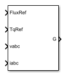
Ports
Input
Output
Parameters
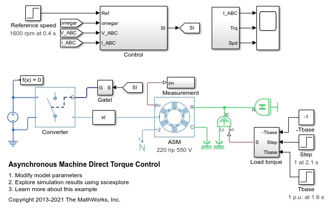
Model Examples
References
[1] Takahashi, I., and T. Noguchi. "A New Quick-Response and High-Efficiency Control Strategy of an Induction Motor."IEEE Transactions on Industry Applications. Vol. IA-22, Number 5, 1986, pp. 820 - 827.
Extended Capabilities
版本历史
See Also
Blocks
- Induction Machine Current Controller|Induction Machine Direct Torque Control (Single-Phase)|Induction Machine Direct Torque Control with Space Vector Modulator|Induction Machine Field-Oriented Control|Induction Machine Field-Oriented Control (Single-Phase)|Induction Machine Flux Observer|Induction Machine Scalar Control
You can also select a web site from the following list:
Americas
- América Latina(Español)
- Canada(English)
- United States(English)
Europe
- Belgium(English)
- Denmark(English)
- Deutschland(Deutsch)
- España(Español)
- Finland(English)
- France(Français)
- Ireland(English)
- Italia(Italiano)
- Luxembourg(English)
- Netherlands(English)
- Norway(English)
- Österreich(Deutsch)
- Portugal(English)
- Sweden(English)
- Switzerland
- United Kingdom(English)