Stream Audio Signal from Intel FPGA Board Using Ready-to-Capture Signal
这个例子展示了如何使用一个已经准备好,可以捕获ignal in an FPGA data capture with existing HDL code to read FPGA streaming signals. This example starts with an existing FPGA design that implements an on-chip analog-to-digital converter (ADC) to sample an audio signal. The ADC intellectual property (IP) exposes an Avalon® memory-mapped (MM) slave interface for control and an Avalon streaming interface for data output. The existing example contains a simple Avalon MM master to start the ADC. Use FPGA data capture to collect the ADC output data from the Avalon streaming interface and stream the data to the MATLAB® workspace.

Theready_to_capturesignal is output from the FPGA data capture HDL IP. This ouput captures continuous data provided that you places a first-in first-out (FIFO) in front of the FPGA data capture HDL IP and check theready_to_capturesignal before streaming data to the data capture IP. You might also need to check that the FIFO is not empty. This figure illustrates the continuous data capture workflow.

The audio data from the Avalon streaming interface is written into a FIFO, and the FIFO is read when theready_to_capturesignal is asserted. To avoid data overflow, the FIFO must be large enough to capture data whenready_to_captureis deasserted. In this example, the FIFO depth is configured to 16 k and the audio sampling frequency is 50 kHz.
Requirements and Prerequisites
MATLAB
HDL Verifier™
HDL Verifier Support Package for Intel® FPGA Boards
Fixed-Point Designer™
Intel Quartus® Prime software with a supported version listed inSupported EDA Tools and Hardware
Arrow® DECA MAX® 10 FPGA Evaluation Kit
DSP System Toolbox™
Set Up FPGA Development Board
1. Confirm that the power switch is off.
2. Connect the JTAG download cable between the FPGA development board and the host computer.
3. (Optional) Connect the line-in port of the FPGA board with an audio source, such as your cellphone, via 3.5 mm audio cable. If you skip this step, the captured data will be random noises.
Prepare Example Resources
Set up the Intel Quartus. This example assumes that the Intel Quartus executable is located in the fileC:\altera\18.0\quartus\bin\quartus.exe。如果你的可执行文件的位置是不同的,use your path instead.
hdlsetuptoolpath('ToolName','Altera Quartus II','ToolPath','C:\altera\18.0\quartus\bin\quartus.exe');
Generate FPGA Data Capture Components
Launch theFPGA Data Capture Component Generatortool by executing this command in MATLAB.
generateFPGADataCaptureIP
This example monitors one signal from the existing HDL code for the audio system. The signal is a 12 bitadc_out。Theadc_outsignal is the digital samples of the audio line-in signal. To configure the data capture components to operate on this signal, follow these steps.
1. Name the signal toadc_outin thePortstable.
2. Change the bit width of the signal to 12.
3. SelectFPGA vendorasAltera。
4. SelectGenerated IP languageasVerilog。
5. SelectSample depthas8192。This value is the number of samples of each signal that the data capture tool returns to MATLAB each time a trigger is detected.
This figure shows these tool settings.

To generate the FPGA data capture component, clickGenerate。A report shows the results of the generation.
Integrate FPGA Data Capture HDL IP
You must include the generated HDL IP core into the example FPGA design. You can copy the module instance code from the generated report. In this example, connect the generated HDL IP with the ADC output via a FIFO.
Open thereadyToCapture_top.vfile provided with this example. Uncomment this code.
datacaptureu0(。clk(clock), .clk_enable(adc_valid), .ready_to_capture(ready_to_capture), .adc_out(adc_out) );
SavereadyToCapture_top.v, compile the modified FPGA design, and create an FPGA programming file by using the following Tcl script.
system('quartus_sh -t readyToCapture_deca_max10.tcl &')
The Tcl scripts that are included in this example perform these steps.
1. Create a new Quartus project.
2. Add example HDL files and the generated FPGA data capture HDL files to the project.
3. Compile the design.
4. Program the FPGA.
Wait until the Quartus process successfully finishes before going to the next step. This process takes approximately 5 to 10 minutes.
Capture Data
Navigate to the directory where the FPGA data capture component is generated.
cd hdlsrc
You must set the capture mode toImmediateto use a ready-to-capture signal in an FPGA data capture. To capture data in the immediate mode, follow these steps.
1. Create an FPGA data capture System object™ and configure these properties.
DataCaptureObj = datacapture; DataCaptureObj.TriggerPosition = 0; DataCaptureObj.NumCaptureWindows = 1; setRunImmediateFlag(DataCaptureObj,'1')
2. Capture FPGA data continuously. In this example, captureNumberOfSampledepthsnapshots of data. You can modify theNumberOfSampledepthvalue as needed.
NumberOfSampledepth = 10; Sample_depth = 8192; adc_out = int16(zeros(NumberOfSampledepth*Sample_depth, 1));fori=1: NumberOfSampledepth adc_out( i*Sample_depth-(Sample_depth-1) :i*Sample_depth) = step(DataCaptureObj);end
3. Save the captured audio data by writing the captured data to。wavformat. Process or replay the captured data at a later time.
audiowrite('captured_audio_file.wav',adc_out,50000)
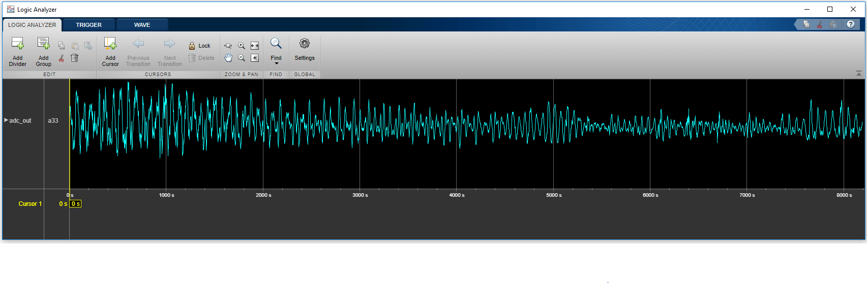
4. View the captured data in theLogic Analyzertool. TheLogic Anlayzertool can take a few seconds to load the captured snapshots of data.
scope = dsp.LogicAnalyzer('NumInputPorts',1,'DisplayChannelFormat','Analog','DisplayChannelHeight',100); tags = getDisplayChannelTags(scope); modifyDisplayChannel(scope,tags{1},'Name','adc_out'); scope(adc_out);
This figure shows 8 k samples of audio data in theLogic Analyzertool.
See Also
FPGA Data Capture Component Generator|FPGA Data Capture
Related Topics
Select a Web Site
Choose a web site to get translated content where available and see local events and offers. Based on your location, we recommend that you select:。
Selectweb siteYou can also select a web site from the following list:
Americas
- América Latina(Español)
- Canada(English)
- United States(English)
Europe
- Belgium(English)
- Denmark(English)
- Deutschland(Deutsch)
- España(Español)
- Finland(English)
- France(Français)
- Ireland(English)
- Italia(Italiano)
- Luxembourg(English)
- Netherlands(English)
- Norway(English)
- Österreich(Deutsch)
- Portugal(English)
- Sweden(English)
- Switzerland
- United Kingdom(English)