Design Current and Position Scaling Subsystems
Use these steps to design the current and position scaling subsystems:
Create the current scaling subsystem.
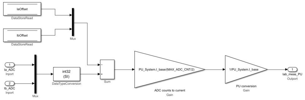
This subsystem reads the current in ADC counts and converts it to per-unit (PU) values.
In this subsystem, theIaOffsetandIbOffsetData Store Memoryblocks are the ADC offsets for current measurement and they are hardware specific. The file
mcb_SetInverterParameters.mcontains the default ADC offset (CtSensAOffsetandCtSensBOffset) for few commercially available inverters. For details about ADC offset calibration in hardware, seeRun 3-Phase AC Motors in Open-Loop Control and Calibrate ADC Offset.In this subsystem, the motor phase current measured in ADC counts is converted to current in PU. The
PU_System.I_basevalue refers to the base current in this subsystem. For details about the PU system, seePer-Unit System. See themcb_SetPUSystem.mfile that computes the PU values for the system.You can use the base values for computing the real-world values from per-unit. To implement the real-world or SI unit values, see the model
mcb_pmsm_foc_qep_f28379d_SIUnitused in the exampleField-Oriented Control of PMSM Using SI Units.TheIaOffsetandIbOffsetData Store Memoryblocks are used to share data between the current and position subsystems.
Create the position scaling subsystem.

This subsystem reads the rotor position from the QEP pulse count.
In this subsystem, theQuadrature Decoderblock reads the position count from the plant model or hardware driver block. The block converts the rotor mechanical position in encoder position counts to rotor mechanical angle in PU (
0-1).TheMechanical to Electrical Position(Mech2Elec Position) block adjusts the rotor mechanical angle for QEP offset and converts it to electrical angle. The FOC algorithm needs the rotor electrical angle to run the motor. To calculate the QEP encoder offset, seeQuadrature Encoder Offset Calibration for PMSM Motor.
TheSpeed Measurementblock calculates speed from the rotor position. In theSpeed Measurementblock parameters dialog box, set theDelays for speed calculation (number of samples)parameter to
20. We selected the value20在这个工作流程,以便车辆ck can measure the maximum speed of the motor that is under test. TheSpeed Measurementblock outputs the speed in PU.


The resulting two subsystems (Calculate Phase Currents and Calculate Position and Speed) contain the current scaling and position decoding logic.

Select a Web Site
Choose a web site to get translated content where available and see local events and offers. Based on your location, we recommend that you select:.
Selectweb siteYou can also select a web site from the following list:
Americas
- América Latina(Español)
- Canada(English)
- United States(English)
Europe
- Belgium(English)
- Denmark(English)
- Deutschland(Deutsch)
- España(Español)
- Finland(English)
- France(Français)
- Ireland(English)
- Italia(Italiano)
- Luxembourg(English)
- Netherlands(English)
- Norway(English)
- Österreich(Deutsch)
- Portugal(English)
- Sweden(English)
- Switzerland
- United Kingdom(English)