理解模型预测控制,第6部分:如何用Simulink和模型预测控制工具箱设计MPC控制器金宝app
从系列:了解模型预测控制
Melda Ulusoy, MathWorks
学习如何使用模型预测控制工具箱设计自动车辆转向系统的MPC控制器。
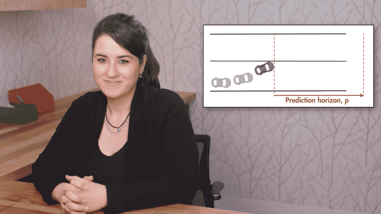
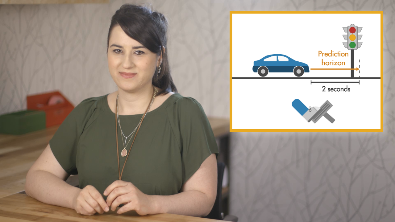
本视频将带您了解MPC控制器的设计过程。使用模型预测控制工具箱附带的MPC设计器应用程序,您可以指定MPC设计参数,如控制器采样时间、预测和控制范围、约束和权重。然后,您可以微调控制器并评估其性能。对于本视频中演示的自动转向车辆示例,使用自动驾驶工具箱™中的Driving Scenario Designer应用程序创建一个自定义参考轨迹。
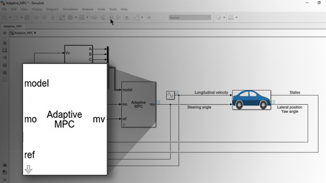
在这个视频中,我们将使用MPC Designer应用程序来设计一个MPC控制器,在变道机动场景中自动驾驶汽车。让我们从这个系统的参数开始。汽车的全局位置是相对于X和Y轴表示的。这些矢量显示了汽车的纵向和横向速度。在这个控制问题中,我们希望汽车沿着参考轨迹行驶。我们需要控制的是横向位置和偏航角。我们要通过调整转向角度来做到这点。横向位置和偏航角的参考值是相对于水平轴计算的。在这个例子中,我们将假设恒定的纵向速度为15米/秒,并使用线性化的汽车模型来表示横向车辆动力学。有关更多信息,请查看视频描述中给出的链接,该链接将带您到这个模型预测控制工具箱示例。
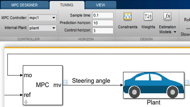
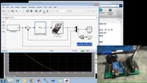
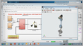
让我们切换到Simulink来构金宝app建自动转向控制系统。这是我们要构建的标准MPC控制图。我们将从添加植物到我们的模型开始。在这里,我有一个自定义库,其中包括我之前创建的块。植物是其中之一,并已发展为状态空间模型的横向车辆动力学。转向装置的输入是转向角,两个输出是横向位置和偏航角。现在,我们要连接MPC控制器,你可以在模型预测控制工具箱中找到它。这个块的第一个输入是测量的输出。我们把输出连接起来。第二个输入是参考。 In this example, we want to simulate a car changing lanes. To create a custom reference trajectory for such a scenario, I’m going to use the Driving Scenario Designer that is part of Automated Driving Toolbox. Using this app, I create a road with two lanes that are 4 meters wide, then add a car and add waypoints to generate the lane-change maneuver. You can adjust the waypoints manually from the side panel if needed. The car’s speed is set to 15 m/s. If I now simulate this scenario step by step, the app shows me how the yaw angle changes. I exported this scenario as a MATLAB function and created a block that outputs the reference lateral position and yaw angle values. I add this custom reference to my model and connect it to the controller. Here, we assume there are no measured disturbances, so we’ll remove the third input. Now that we connected all system components, we’ll continue designing the MPC controller. For this, we open the MPC block and click on “Design,” which opens up the MPC Designer. The MPC Designer is an interactive tool that lets you design MPC controllers and is shipped as part of Model Predictive Control Toolbox. Remember in the previous videos we talked about MPC design parameters such as sample time, prediction and control horizons, and constraints and weights. You can specify all these parameters in the MPC Designer, tune the controller, and then evaluate the controller’s performance. Now, we’ll go back to the MPC Designer and start by defining the MPC structure. We’ll enter the number of manipulated variables and measured outputs, and set the controller sample time to 0.1s. Then we click “define and linearize.” Remember that MPC uses an internal plant model to make predictions and an optimizer to find the optimal control action. Now, when we click “define and linearize,” the app imports and linearizes the plant from the Simulink model and uses it as the internal plant model. It also runs the default simulation scenario and displays the input and output responses. Next, we click on the I/O Attributes to type in the signal labels and units. Note that if these signals differ too much in magnitude, for example, say one is around 1 and the other one is around 1000, then you can use scale factors to bring them to similar scale. We’ll keep the default values for this example as the magnitude difference is not too much. Next, we’ll edit the default scenario. We can choose different types of reference signals from these options. The closest to our lane change scenario would be a ramp input for the lateral position reference and a constant reference of zero for the yaw angle to minimize it. We click OK and this updates the responses. Next, we’ll switch to the tuning tab where we can specify MPC design parameters. These are the default values for prediction and control horizons. Let’s see how the system behavior changes for a larger prediction horizon. For 15 and 20, the response looks more sluggish, so we will set it back to 10. Next, we’ll play with the control horizon. Increasing it to 3 provides a better control of the lateral position. If we increase it further, it doesn’t affect the response significantly, so we settle on a control horizon of 3.
接下来,我们将设置约束。输入约束是由车辆的物理限制决定的。在这个例子中,我们假设方向盘最大可以转向30度,因此我们将输入/6弧度作为输入约束。为了让驾驶员感到舒适,我们将把转向角度的变化速率限制在15度/秒。请注意,默认情况下,所有的输入约束都是硬的,而输出约束是软的。我们将尽量使输出保持在这些值之间。接下来,我们将指定权重。如果我们希望输入和输出有一个目标,我们需要将权重设置为一个非零值。对于转向角度,我们将保持默认权重为零,因为它不需要跟踪目标。我们还将为输入速率保留默认权重。 You can increase this weight if you want to have even smaller input increments. And for the outputs, we’ll set the weight for the lateral position to 1 and the yaw angle weight to 0.1, as position tracking is our primary objective. After setting all these parameters, you can fine tune your controller by using this slider. We’ll slide it right for a more aggressive control. And the response looks good.
现在我们已经对控制器的性能感到满意了,我们点击“导出控制器”,它将更新MPC控制器块并运行模拟。注意,在我们的Simulink模型金宝app中,我们使用了之前为变道场景设计的自定义参考。现在我们来看看模拟结果。我们对两个输出都得到了满意的跟踪。并且通过控制器将转向角度控制在一定范围内。
在这个视频中,我们已经走过了MPC控制器的设计过程,但让我也提到,在发布2018a有一个Lane Keep辅助系统块,有效地简化了设计过程。点击视频描述中的链接了解更多。
我们展示了设计的控制器性能良好,但请注意,我们使用的汽车动力学在特定的操作条件下工作,即纵向速度为15米/秒。然而,如果汽车的纵向速度在行驶过程中发生变化,汽车的动力也会发生变化。所以,如果我们现在把速度改为35米/秒,这将导致控制器退化。为了解决这个问题,我们需要设计一个自适应MPC控制器,该控制器将更新内部电厂模型,以适应不断变化的运行条件。这是我们下个视频要讨论的。
产品集中
其他资源


相关视频和网络研讨会


你也可以从以下列表中选择一个网站: