理解模型预测控制,第7部分:使用Simulink和模型预测控制工具箱的自适应MPC设计金宝app
来自系列:了解模型预测控制
Melda Ulusoy, MathWorks
在本视频中,您将学习如何为自动转向车辆系统设计自适应MPC控制器,其动态随纵向速度变化。
设计用于控制系统最可能运行条件的MPC控制器后,您可以基于该设计实现自适应MPC控制器。在每次步骤中,Adaptive MPC更新当前操作条件的工厂模型和标称条件。在此视频中,您将学习如何计算和更新Adaptive MPC块所需的离散工厂模型。您还将了解如何从Adaptive MPC控制器生成代码,您可以看到一个示例,显示使用MPC控制和图像处理算法以保持其车道内的真实自动驾驶汽车。
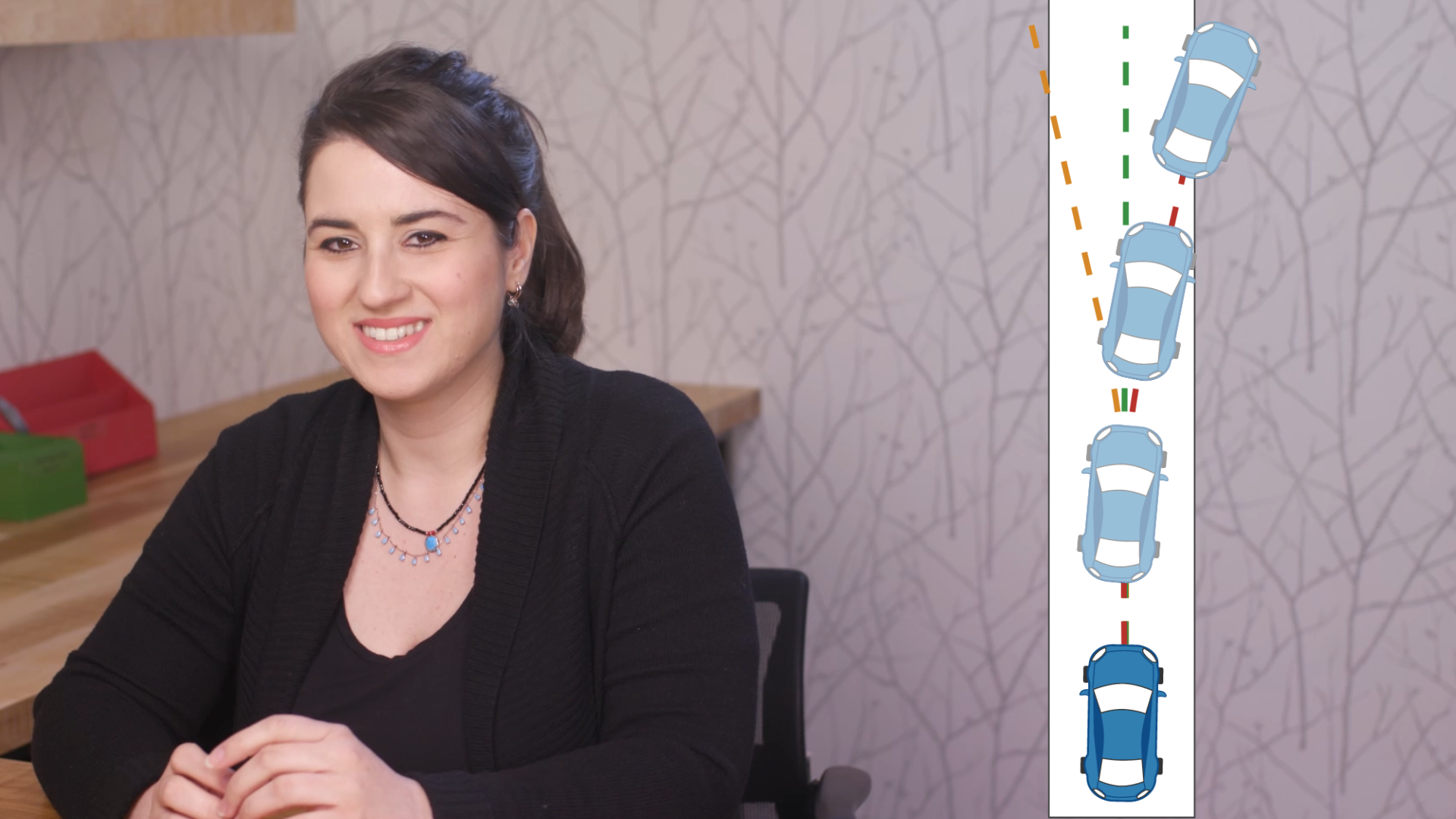
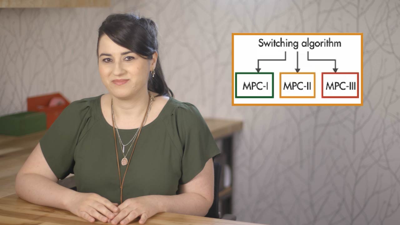
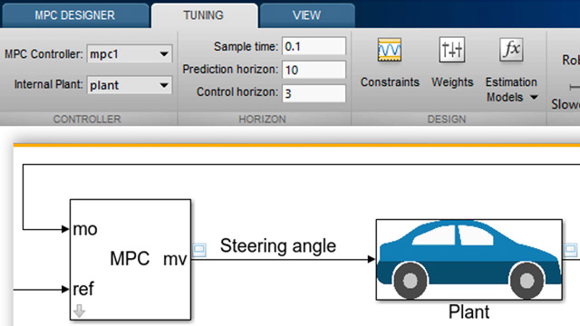
在这个视频中,我们将使用自适应MPC来自动驾驶汽车,由于纵向速度的变化,车辆的横向动力学随时间而变化。在之前的视频中,我们讨论了车辆的线性横向动力学并假设汽车具有恒定的纵向速度。所以,植物的动态是不变的状态矩阵A是不变的。为了控制该系统,我们采用了传统的MPC控制器。但现在我们让纵向速度随着汽车的行驶而变化。所以状态矩阵A也会改变。传统的MPC控制器在处理动态变化方面并不有效,因为它使用的是一个恒定的内部对象模型。那么,我们如何应对不断变化的植物动态呢?在第4部分视频中,我们讨论了自适应MPC可以让你在运行条件变化的每个时间步骤中提供一个新的线性电厂模型,因此它可以在新的运行条件下做出更准确的预测。因此,为了应对不断变化的植物动态,我们将使用适应性MPC。
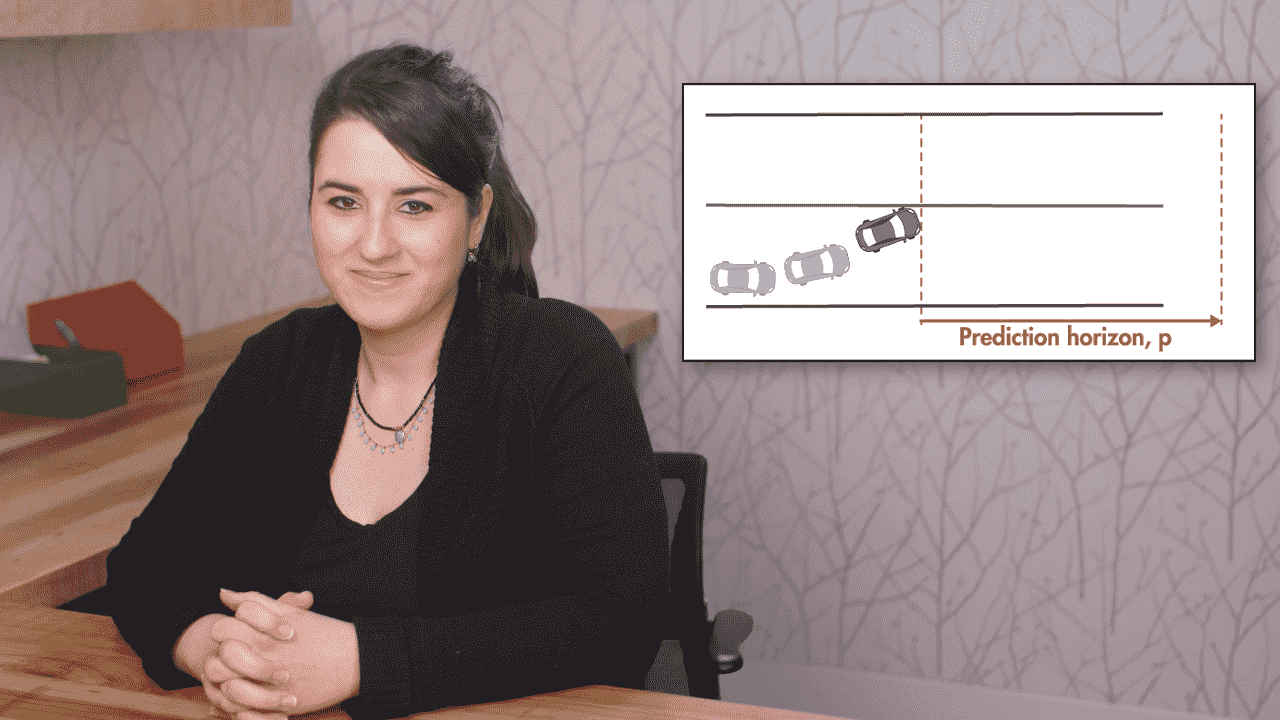
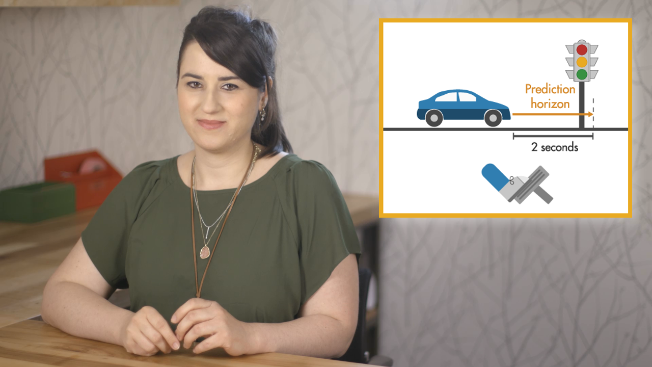
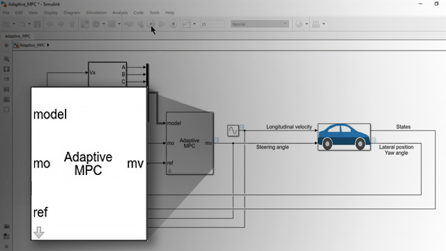
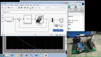
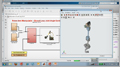
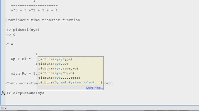
我们打开一个新的Simuli金宝appnk模型,并首先添加来自此自定义库的工厂。如在先前的视频中,该工厂被开发为状态空间系统,具有输入转向角和横向位置和横摆角的输出。这次动态随着纵向速度而变化。因此,这现在成为植物块的输入。我们将为纵向速度连接恒定的块,我们最初将设置为15米/ s并稍后将其更改为另一个值。另一个输出是我们稍后将使用的状态。如果您想在块下看,以查看它们是如何构建的,可以从视频描述中给出的链接下载此Simulink模型。金宝app接下来,我们将连接模型预测控制工具箱下的自适应MPC块。该块具有与常规MPC块相同的输入和输出,不同之处在于它还采用在当前操作条件的每次执行时更新的工厂模型。以前,我们为横向位置和偏航角设计了一种自定义参考。 We’ll first connect this reference to the controller. Then we connect the plant output to the measured outputs and the steering angle to the controller output. To implement the adaptive MPC, we can simply start with the MPC controller that we designed in the previous video for a longitudinal velocity of 15 m/s. We already have the MPC controller object in our workspace. By typing it in the command window, we can see the design parameters such as the prediction and control horizons, constraints and weights. One thing to note is that the adaptive MPC block requires a discrete plant model. So, we need to convert the continuous time state space model used by mpc1 to discrete time. There are different ways to do it. Here, we use the c2d command and update the plant model of the MPC object with the discretized plant. Now, we go back to the adaptive MPC block and type in the MPC object. Next, we need to provide the controller with a plant model that is updated at each time step for the current operating condition. The pre-built update plant model block takes care of this calculation. When we double click on it, we see that it has been implemented as a MATLAB function. As inputs, this function takes Vx, u and x and first calculates the state space matrices. It then computes the discrete model and also updates the nominal conditions with the current operating conditions. Now it’s time to connect the inputs and outputs for this block. We already have all the inputs here, longitudinal velocity, the steering angle and the states. The “model” input of the adaptive MPC control block requires the discrete-time model and nominal conditions in this order that we’ve created in the MATLAB function. To connect the outputs to the controller, we select the block, and create a bus signal. Now, we’re ready to try different longitudinal velocities and see how the controller handles the varying plant dynamics. In the previous video, the traditional MPC controller designed for an operating condition of 15 m/s had worked well while it failed to control the system at a different longitudinal velocity of 35 m/s. With adaptive MPC, we get a good controller performance when longitudinal velocity is 15 m/s. If we now change it to 35 m/s, we still get a good tracking of the lateral position and the yaw angle. We can even replace this constant block with a continuously changing signal such a sine wave and see that adaptive MPC still can deal with the changing plant dynamics and successfully control the system. We designed an adaptive MPC controller, ran several simulations to evaluate the controller performance. Now if you want to run your controller on your autonomous car, you can simply generate code using Embedded Coder and deploy it to your car. Here’s the generated C code. You can call the MPC controller code from your real-time scheduler using the entry points shown in the code interface report. Embedded Coder also lets you customize the call interfaces as required by your software framework and architecture.
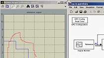
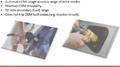
此视频在此示出了MPC控制器的代码如何生成的示例以及在自动驾驶汽车上运行的图像处理算法以将其保持在车道内。在Simulink外部开发的图像处理和车道检测算法为MPC控制器提供了这些输入。金宝app以下是这些算法的工作原理。汽车的正视图是用安装在汽车顶部的相机捕获。The image processing algorithm identifies the solid and dashed line markings, and detects the lane the car is traveling in. The middle of the lane is the centerline and it is used to compute the offset of the car’s position from this line as well as the yaw angle. This information is used by the MPC controller that tries to keep the car on the centerline. The plot on the left shows the deviation of the car from the centerline with red and yaw angle with green whereas the plot on the right shows the steering angle.
在本视频中,我们讨论了如何使用自适应MPC来控制不断变化的动态,也讨论了如何生成C代码并部署它进行实时控制。有关模型预测控制的更多信息,请查看我们之前的Tech Talk视频。
产品集中
其他资源

相关视频和网络研讨会


您还可以从以下列表中选择一个网站: